Circuit Descriptions
1502C MTDR Service Manual
5–13
Label
Option Port
(D-Connector)
J2010
(on Main Board)
IA
11 6
IR4
13 7
R-T TRIG
2 14
SW+16
25
23
13
12
+16
RTN
21
19
11
10
SW+5
17 9
+5
RTN
4
15
15
8
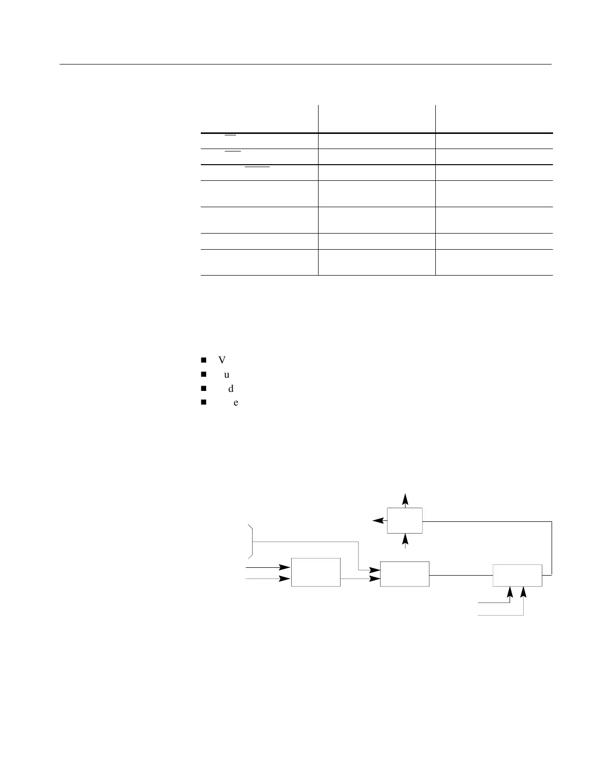
Video Processor
The video processor system consists of the following:
H
Vertical Position DAC
H
Summing Amplifier
H
Video Amplifier
H
Video DAC
The video processor receives sampled video from the driver/sampler and outputs a
digitized video signal to the processor system data bus. A block diagram of the video
processor is shown in Figure 5–6.
Sampled Video
from
Driver/Sampler
DATA
CONTROL
VIDEO
ADC
SUMMER
AMPLIFIER
VERTICAL
POSITION
DAC
DATA
BUS
CONTROL
INTERRUPT
REQUEST
VIDEO
AMPLIFIER
DATA
CONTROL
COMBINED
VIDEO
Figure 5–6: Video Processor Block Diagram
Vertical position information is loaded by the processor system into a DAC to
generate a DC signal. Sampled video is combined with this vertical position DC
voltage in a summing amplifier in order to allow vertical positioning of the
displayed waveform.
Introduction
Artisan Technology Group - Quality Instrumentation ... Guaranteed | (888) 88-SOURCE | www.artisantg.com