Circuit Descriptions
5–12
1502C MTDR Service Manual
NOTE. There are specified limits to this type of circuitry. Load specifications must
be followed.
The arrangement of the +5 VDC switch is similar except that a 10 k
W
to 100
k
W
resistive divider is used to ensure the switch has a definite turn-on. A single FET,
Q1010, controls the +5 VDC output.
Data lines to the option port pass through the bus transceiver, U2011. Address lines
RD’
and WR’ are driven by U2012. CS22, from the processor system, enables these
drivers with RD
controlling the transceiver direction. U2012 outputs are pulled up
by the switched +5 VDC supply, via R2015. The data lines are pulled down via
R2014.
WR’
is a modified write pulse 200 ns long, created to give a rising edge prior to the
disabling of the drivers. This pulse is created by flip-flop U2033A.
The output latch U1011A is controlled by A
0
and A
1
, with select signal CS10. The
output of this latch is optionally used in the interface protocol.
Two more lines are used in the option port interface. IR4
is an interrupt signal that
is active low when creating processor interrupts. R-T TRIG
is also available at the
interface. This is the trigger pulse generated in the analog timebase.
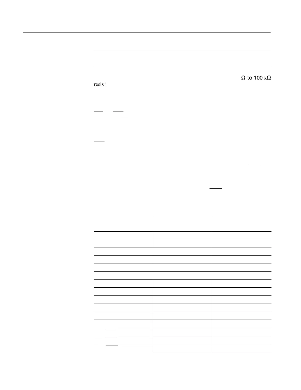
Label
J2010
(on Main Board)
Option Port
(D-Connector)
D
0
3 2
D
1
1 1
D
2
24 25
D
3
22 24
D
4
20 23
D
5
18 22
D
6
16 21
D
7
14 20
A
0
’
12 19
A
1
’
10 18
A
2
’
8 17
A
3
’
6 16
RD’
7 4
WR’
5 3
CS22
9 5
Buffers
Output Latch
Option Port Wiring
Configuration
Artisan Technology Group - Quality Instrumentation ... Guaranteed | (888) 88-SOURCE | www.artisantg.com