Operating Instructions
1–24
1502C MTDR Service Manual
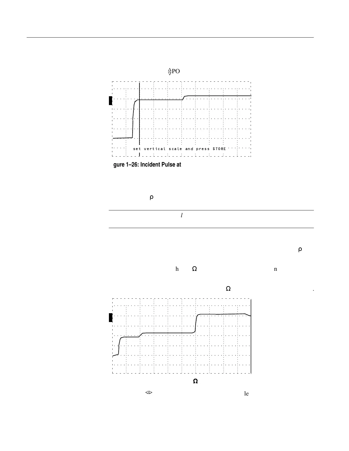
2. Adjust the incident pulse to the desired height (e.g., four divisions). It might be
necessary to adjust
n
o
POSITION.
O
F
F
O
F
F
O
F
F
O
N
ac 0.000 ft
set vertical scale and press STORE
Figure 1–26: Incident Pulse at Three Divisions
3. Push STORE.
4. Return NOISE FILTER to the desired setting. Notice that the vertical scale now
reads 500 m
r
/div.
NOTE. The millirho vertical scale will not be in calibration after arbitrarily
adjusting the pulse height.
The millirho scale is the reciprocal of the number of divisions high the pulse has
been set. For example, 1 pulse divided by 4 divisions equals 0.25 or 250 m
r
/div.
When testing cables other than 50
W
, this procedure allows reflection measurements
in millirho.
1. Attach a short sample of the given cable (75
W
in this example)to the instrument.
O
F
F
O
F
F
O
F
F
O
N
ac 19.200 ft
Figure 1–27: Waveform of Short 75
W
Cable
2. Adjust the
POSITION control to position the reflected pulse at center screen.
3. Turn NOISE FILTER to VERT SET REF.
Vertical Compensation for
Higher Impedance Cable
Artisan Technology Group - Quality Instrumentation ... Guaranteed | (888) 88-SOURCE | www.artisantg.com