Calibration
6–6
1502C MTDR Service Manual
7. Rotate DIST/DIV counterclockwise to its far stop. The switch reading on the
display should be 15.
8. Slowly rotate this control clockwise to its far stop. Each position should
increase the switch reading one count, starting at 15 and ending with 25.
9. The display should currently show a V
P
of 0.30. Slowly rotate the left V
P
control
to full clockwise. Each click should correspond to the front-panel control
setting.
10. Rotate the right V
P
control to full clockwise. Again, the LCD reading should
match the front-panel control setting. The final reading with both controls fully
clockwise should be 0.99.
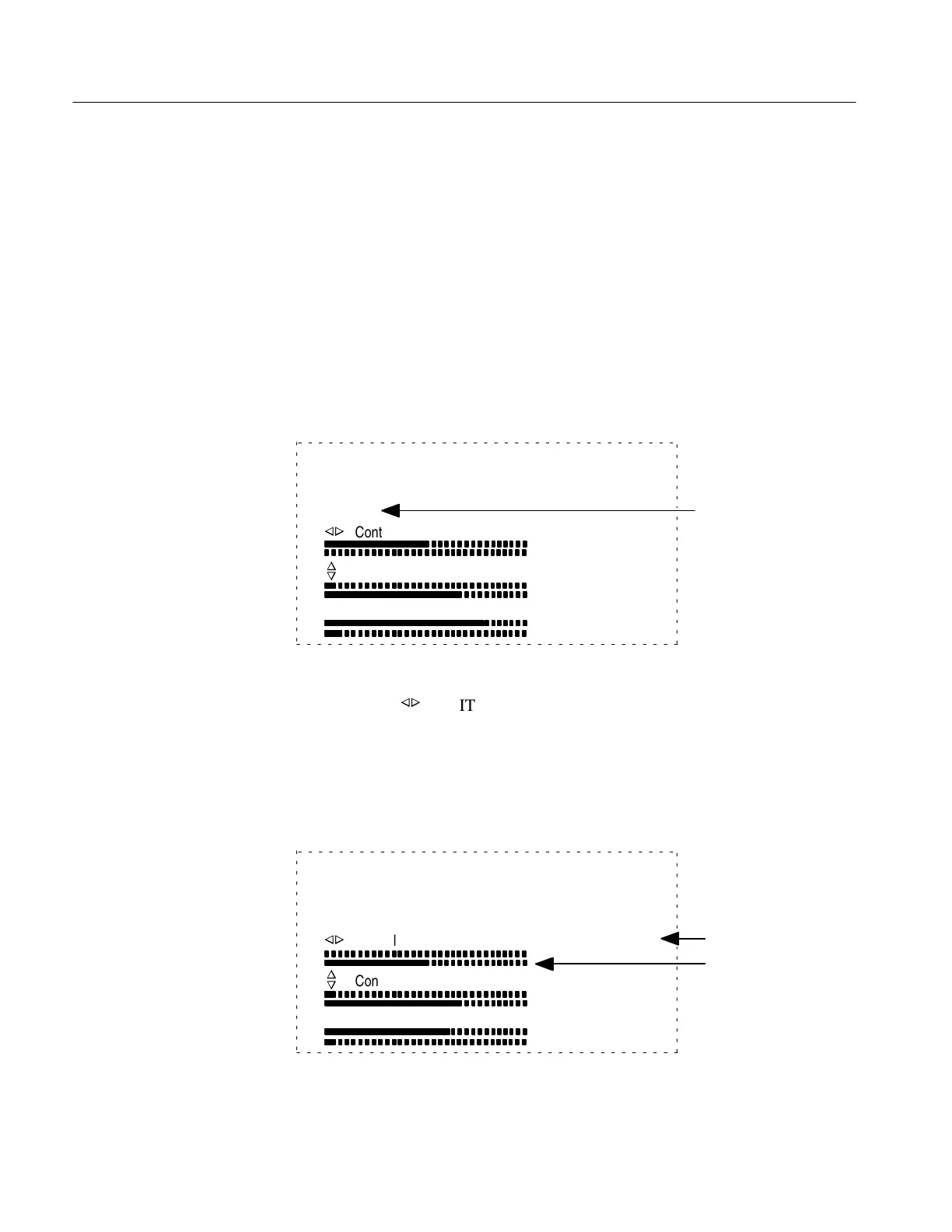
Front Panel Diagnostic, test all switches.
Hold down MENU button to Exit.
Switch: 1 temp: 84
Vp: 0.30
n
o
n
o
Control
Control
Vertical Scale
142
11
190
0
181
24
Vp Reading
Figure 6–7: Front Panel Diagnostic Display
11. Rotate the
n
o
POSITION control, slowly in either direction. The bar graph
shown on the display represents the two elements of each control. The readings
to the right of the bar graph represent numbers used by the instrument to
calculate the position of the knob. As the control is rotated, these values and the
bar graph will change. The lower value in each column should be between 0 and
10 while the higher number is between 245 and 255.
Front Panel Diagnostic, test all switches.
Hold down MENU button to Exit.
Switch: 35 temp: 82
Vp: 0.99
n
o
n
o
Control
Control
Vertical Scale
0
12
172
142
181
8
Bar Graph
Corresponding
Numbers
Figure 6–8: Front Panel Diagnostic Display
Artisan Technology Group - Quality Instrumentation ... Guaranteed | (888) 88-SOURCE | www.artisantg.com