Calibration
1502C MTDR Service Manual
6–5
Exit Diagnostics Menu
Service Diagnostic Menu
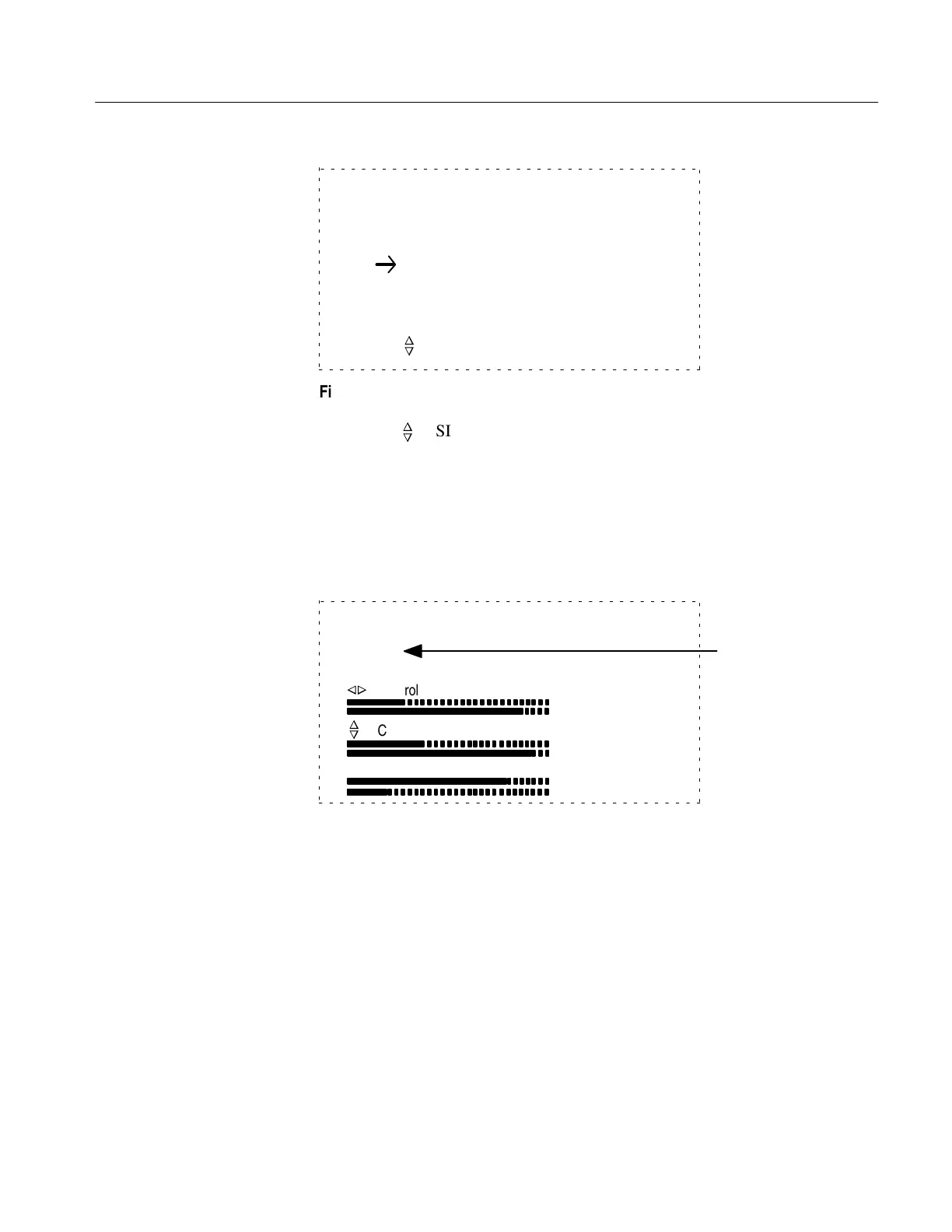
Front Panel Diagnostic
LCD Diagnostics Menu
Chart Diagnostics Menu
Move Position to select, then push MENU button
n
o
Figure 6–5: Diagnostics Menu
6. Use the
n
o
POSITION control to scroll to Front Panel Diagnostic.
7. Press MENU. This will display the Front Panel Diagnostics.
1. Press VIEW INPUT. The LCD switch reading should change to 1 (see Figure
6–6, third line of text).
Front Panel Diagnostic, test all switches.
Hold down MENU button to Exit.
Switch: 1 temp: 85
Vp: 0.30
n
o
n
o
Control
Control
Vertical Scale
76
97
230
253
255
61
Switch Reading
Figure 6–6: Front Panel Diagnostic Display
2. Press VIEW STORE. The LCD switch reading should change to 2.
3. Press VIEW DIFF. The LCD switch reading should change to 3.
4. Press STORE. The LCD switch reading should change to 4.
5. Rotate NOISE FILTER counterclockwise to VERT SET REF. The switch
reading on the display should be 5.
6. Slowly rotate this control clockwise to its far stop. Each position should
increase the switch reading one count, starting at 5 and ending with 14.
Pushbutton Switches
Rotating Controls
Artisan Technology Group - Quality Instrumentation ... Guaranteed | (888) 88-SOURCE | www.artisantg.com