Calibration
1502C MTDR Service Manual
6–11
O
F
F
O
F
F
O
F
F
O
N
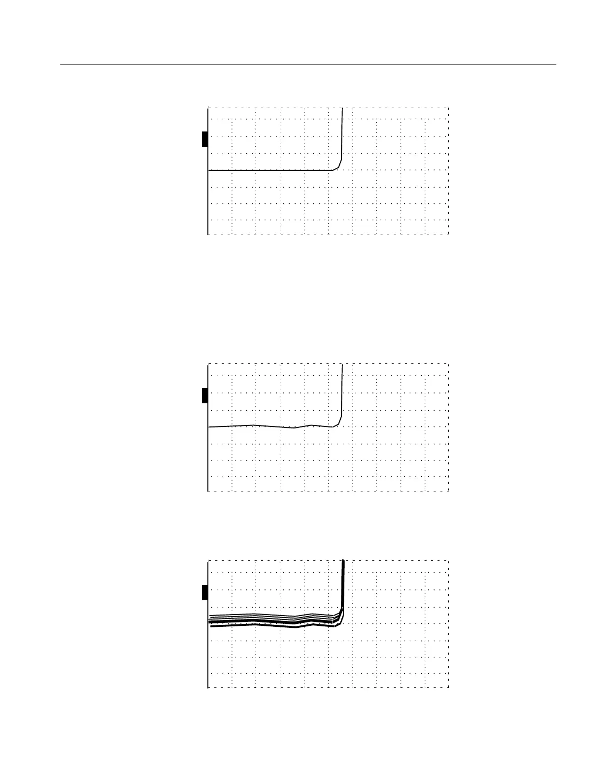
ac –2.000 ft
Figure 6–16: Incident Pulse at –2.000 ft
5. The front panel CABLE connector has a shorting bar that shorts the input when
a cable is removed. Attach the 3-ft precision cable to the CABLE connector to
defeat this shorting bar.
6. Notice any minor changes in the waveform. The waveform prior to the leading
edge might change shape slightly, but should not shift more than one division.
O
F
F
O
F
F
O
F
F
O
N
ac –2.000 ft
Figure 6–17: Incident Pulse at –2.000 ft with 3-ft Cable Connected
Max Hold can be used to easily monitor any changes, as shown below.
O
F
F
O
F
F
O
F
F
O
N
ac
–2.000 ft
Figure 6–18: Incident Pulse at –2.000 ft with Max Hold
Artisan Technology Group - Quality Instrumentation ... Guaranteed | (888) 88-SOURCE | www.artisantg.com