Calibration
6–12
1502C MTDR Service Manual
7. Turn the instrument OFF, then ON again. This will reset it for the next check.
NOTE. If the instrument fails this check,, first refer to Zero Offset Adjust in the
Adjustment Procedures section of this chapter. If you are unable to adjust this
satisfactorily, refer to the Circuit Descriptions chapter and the Troubleshooting
section of the Maintenance chapter of this manual.
Vertical Position (Offset) Check
If the instrument fails only this check, it can be used but should be serviced. Not all
waveforms will be viewable at all gain settings.
1. Set the front-panel controls:
CABLE 3-ft precision cable
NOISE FILTER 1 avg
VERT SCALE 500 m
r
DIST/DIV 1 ft/div
V
P
.99
2. Set the
n
o
POSITION control so the distance window reads –2.000 ft.
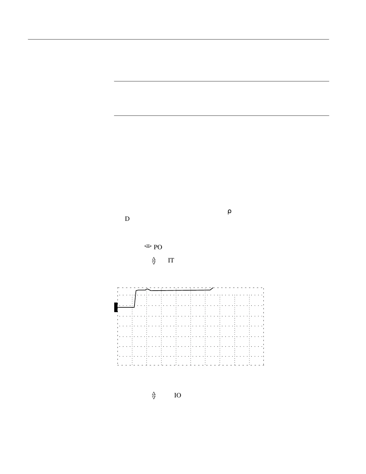
3. Using the
n
o
POSITION control, verify that the entire waveform can be moved
upward past the center graticule line.
O
F
F
O
F
F
O
F
F
O
N
ac
–2.000 ft
Figure 6–19: Waveform at Top of the Display
4. Using the
n
o
POSITION control, verify that the entire waveform can be moved
to the very bottom of the display. The top of the pulse should be lower than the
center graticule line.
Artisan Technology Group - Quality Instrumentation ... Guaranteed | (888) 88-SOURCE | www.artisantg.com