Calibration
6–28
1502C MTDR Service Manual
14 2
113
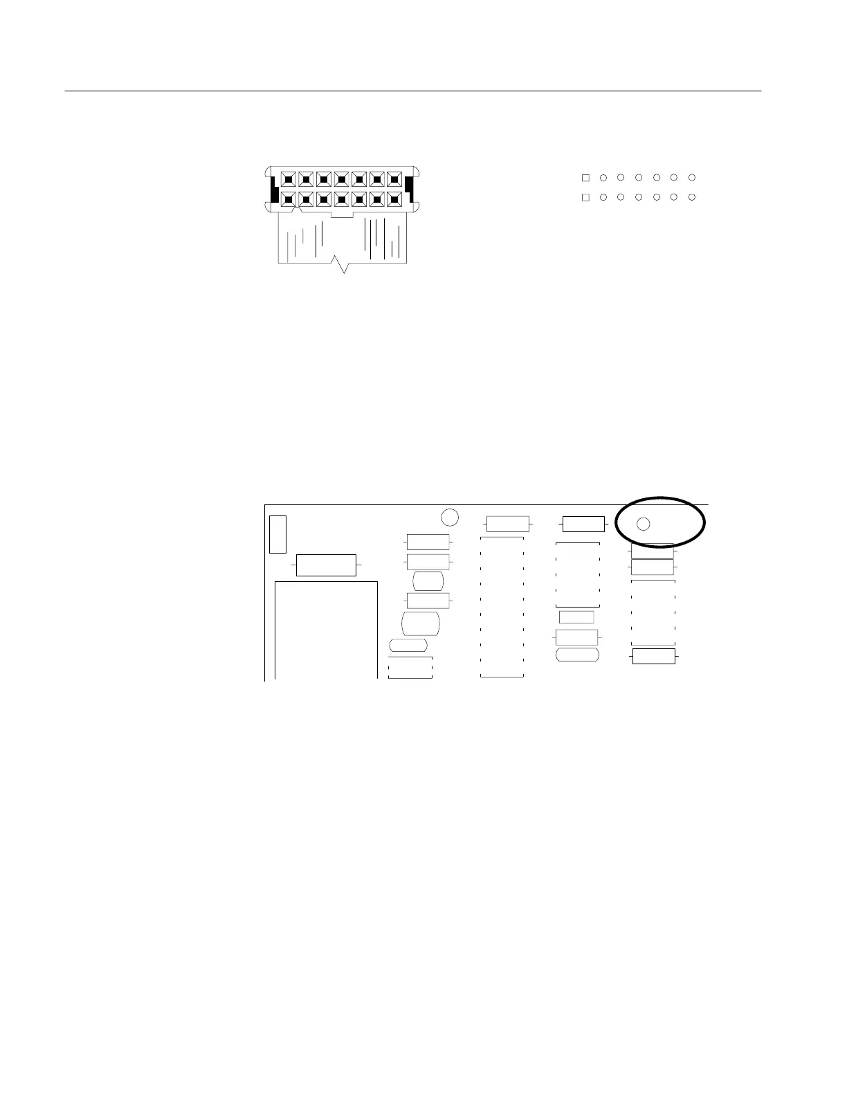
Connector plug P5040
on bottom of Main Board.
Connector pin J5040
on top of Main Board.
142
113
Figure 6–44: Connector Plug P5040 and Pins J5040 on Bottom of Main Board
Test points in this check are located on the Power Supply Board.
1. Connect the positive (+) probe to the +16.6 VDC supply (TP1020) on the Power
Supply Board.
–
J1010
R1010
CR1010
R1011
R1012
C1011
R1013
C1012
C1013
Q1010
R1015
U1010
U1011
VR1012
R1017
C1014
R1016
R1020
R1021
U1020
R1022
TP1020
Figure 6–45: Power Supply Test Point TP1020
2. Change the AC output voltage on the Variac to 132 VAC.
3. Verify that the +16.6 VDC supply remains regulated (+16.4 to +16.8 VDC).
4. Reduce the Variac output voltage to 90 VAC.
5. Verify that the +16.6 VDC supply is still regulated (+16.4 to +16.8 VDC).
6. Move the positive (+) probe to the +16.2 VDC supply (TP2030)
7. Reduce the Variac output voltage until the +16.2 VDC (and the instrument) shut
down. This voltage must be lower than 90 VAC.
Range Check
Artisan Technology Group - Quality Instrumentation ... Guaranteed | (888) 88-SOURCE | www.artisantg.com