Calibration
1502C MTDR Service Manual
6–33
13. Remove the voltmeter probes from the 1502C.
14. Remove the external 12 VDC power supply cable from the battery connector.
15. Reconnect the battery wire to the Power Supply board and to the battery.
16. Connect the AC supply cord to the rear panel.
(with optional battery)
1. Turn the POWER off.
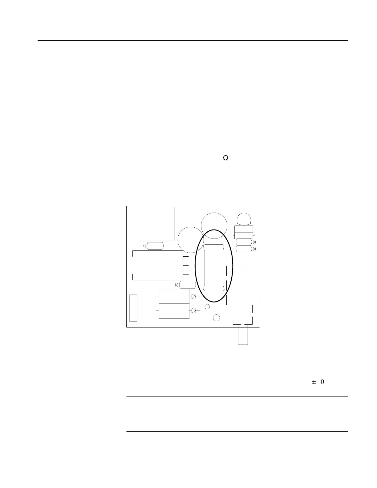
2. Connect a voltmeter across the 4
W
resistor, R2012, located on the Power Supply
Board.
3. Connect the positive (+) probe to the side nearest the front panel and the
negative (–) probe to the other end. The voltage drop across R2012 should be
between 0.4 and 1.2 VDC.
123
U2010
CR2015
CR2011
CR2012
J2010
TP2010
L1010
C2012
C2010
Q1012
R2012
R2011
CR2013
CR2014
S2010
R2012
CR2010
Figure 6–54: R2012 on Power Supply Board
4. Turn the POWER on.
The voltage reading across R2012 should change only slightly (
"
10 mV).
NOTE. The charging current will vary according to the level of charge already on
the battery. With a fully charged battery, the voltage across R2012 should be
approximately 0.4 VDC. With a battery below 11 Volts, R2012 should read
approximately 1.2 VDC.
Charging Current Check
Artisan Technology Group - Quality Instrumentation ... Guaranteed | (888) 88-SOURCE | www.artisantg.com