Operator Performance Checks
1502C MTDR Service Manual
2–7
O
N
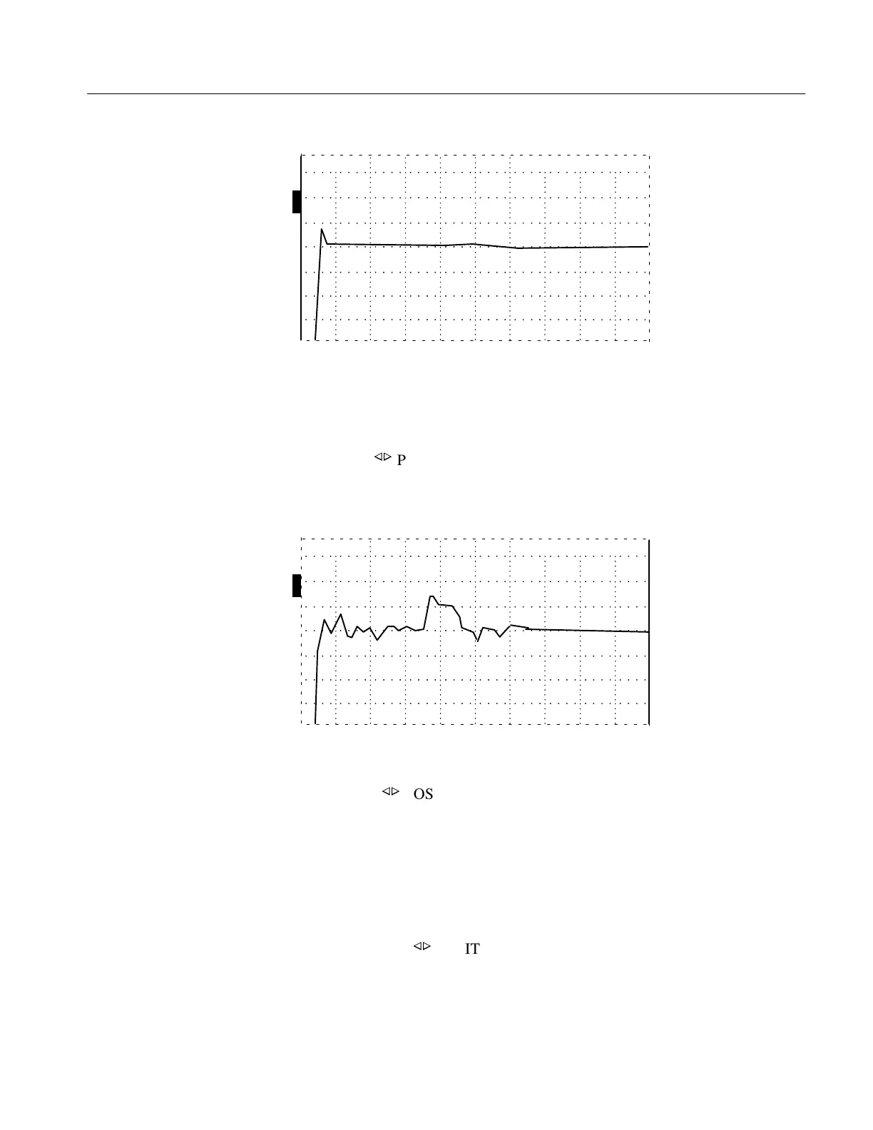
ac –2.000 ft
O
F
F
O
F
F
O
F
F
Figure 2–9: Top of Pulse on Center Graticule
5. Set the DIST/DIV control to 0.2 ft/div (0.05 m/div).
6. Turn the
n
o
POSITION control clockwise until the rising edge of the incident
pulse is in the left-most major division on the display.
O
N
ac 1.160 ft
O
F
F
O
F
F
O
F
F
Figure 2–10: Rising Edge of Incident Pulse in Left-most Major Division
7. Using the
n
o
POSITION control, move the cursor back to 0.000 ft (0.00 m).
All the aberrations, except the one under the cursor (see Figure 2–11), must be
within one division of the center graticule line from out to 10 feet past the rising
edge of the pulse.
To verify distances past the right edge of the display, scroll along the waveform
by turning the
n
o
POSITION control clockwise.
Artisan Technology Group - Quality Instrumentation ... Guaranteed | (888) 88-SOURCE | www.artisantg.com