Circuit Descriptions
5–8
1502C MTDR Service Manual
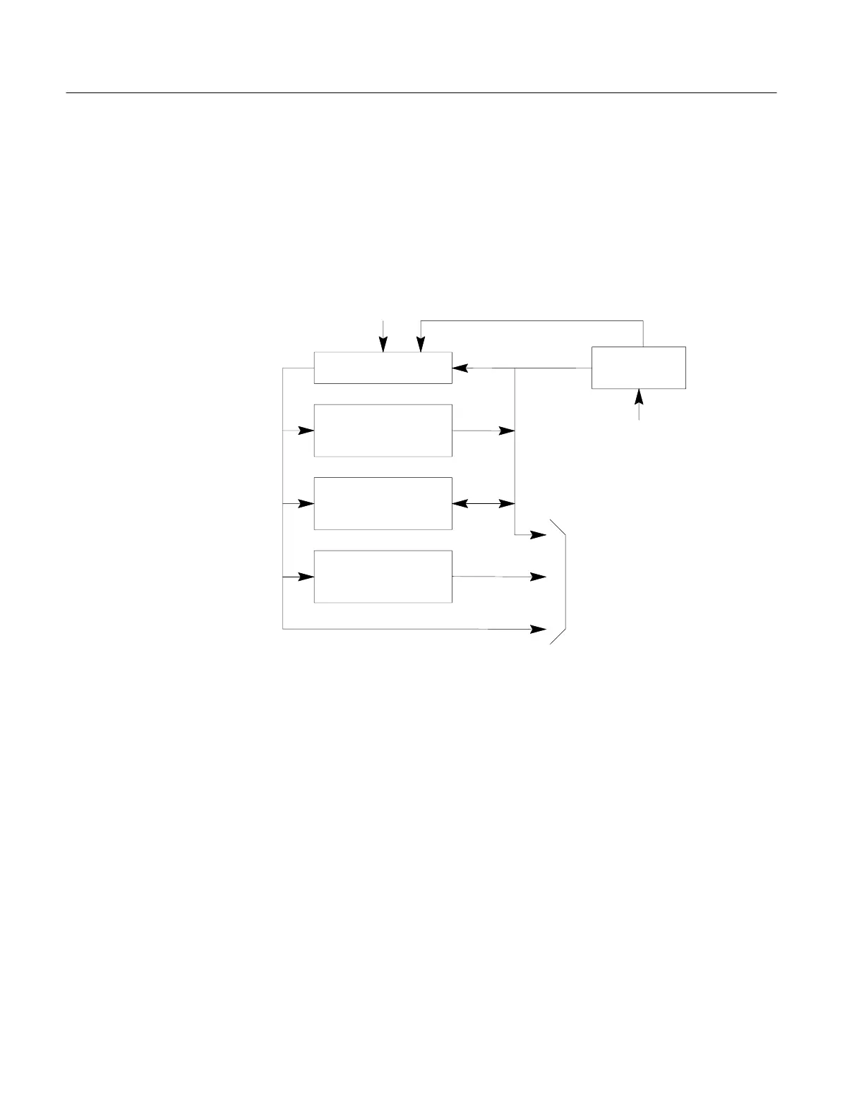
An eight-bit microprocessor, clocked at 5 MHz, provides the processing capability
in a bus-organized system. Instructions are read from the program memory EPROM
and executed by the microprocessor to accomplish essentially all instrument
functions. Random access memory is connected to the microprocessor through its
data and address busses, allowing it to store and retrieve control, video, and display
data, as required.
5 MHz
CLOCK
MICROPROCESSOR
PROGRAM
MEMORY
EPROM
RANDOM
ACCESS
MEMORY
ADDRESS
DECODING
SELECT
DATA
ADDRESS
INTERRUPT
LOGIC
INTERRUPT AND
STATUS INPUTS
DATA SELECT AND
ADDRESS SIGNALS
TO CIRCUITS AND
OPTIONS PORT
Figure 5–4: Processor Block Diagram
The processor communicates with all other instrument circuits via the address, data,
and select signals, and receives requests for service from those circuits via the
interrupt and status signals. Select signals are generated in address decoding circuits
under control of the processor and used to read or write data from a circuit, or to
trigger a circuit function. Interrupts from those circuits are combined in the interrupt
logic to generate an interrupt request to the microprocessor. The processor responds
by reading a data word from this logic to determine the source of the interrupt, or
status data, and then performs the required service routine.
The microprocessor, U1023, is a single chip processor using Z80 architecture
constructed in high-speed CMOS logic. Each data word, or byte, is eight bits wide
and the microprocessor has a 16-bit address capability, allowing it to address up to
65,536 memory locations. The processor’s 5 MHz clock is derived from a crystal
oscillator in the timebase circuits.
When +5 VDC power is applied to C1030 and R1032, the rising voltage
momentarily applies a positive signal to the input of gate U1031B. The resulting
Microprocessor
Artisan Technology Group - Quality Instrumentation ... Guaranteed | (888) 88-SOURCE | www.artisantg.com