Circuit Descriptions
5–16
1502C MTDR Service Manual
The digital portion of the timebase contains a clock generator that develops all
frequencies used in the instrument electronics.
Timebase
DAC
DATA
CONTROL
Analog
Driver
Strobe
Comparator
Voltage
SAMPLER
Cal
Delay
Cal
Ramp
PROCESSOR
CONTROL
Generator
Ramp
Delay
Circuit
Time
Driver
Stobe
PULSE
GENERATOR
RAMP
TRIGGER
DRIVER
TRIGGER
delay cal
50 ns analog
Delay
Counter
Fine
Former
Pulse
TIMEBASE
INTERRUPT
Delay
Counter
Course
Counter
PRT
DATA
CONTROL
DATA
CONTROL
2.5 MHz
2.5 MHz
Generator
Clock
SYSTEM
CLOCKS
20 MHz
5 MHz
2.5 MHz
1.25 MHz
625 KHz
20 MHz
20 MHz
Vref
DIGITAL
TIMEBASE
ANALOG
TIMEBASE
Timebase
Correction
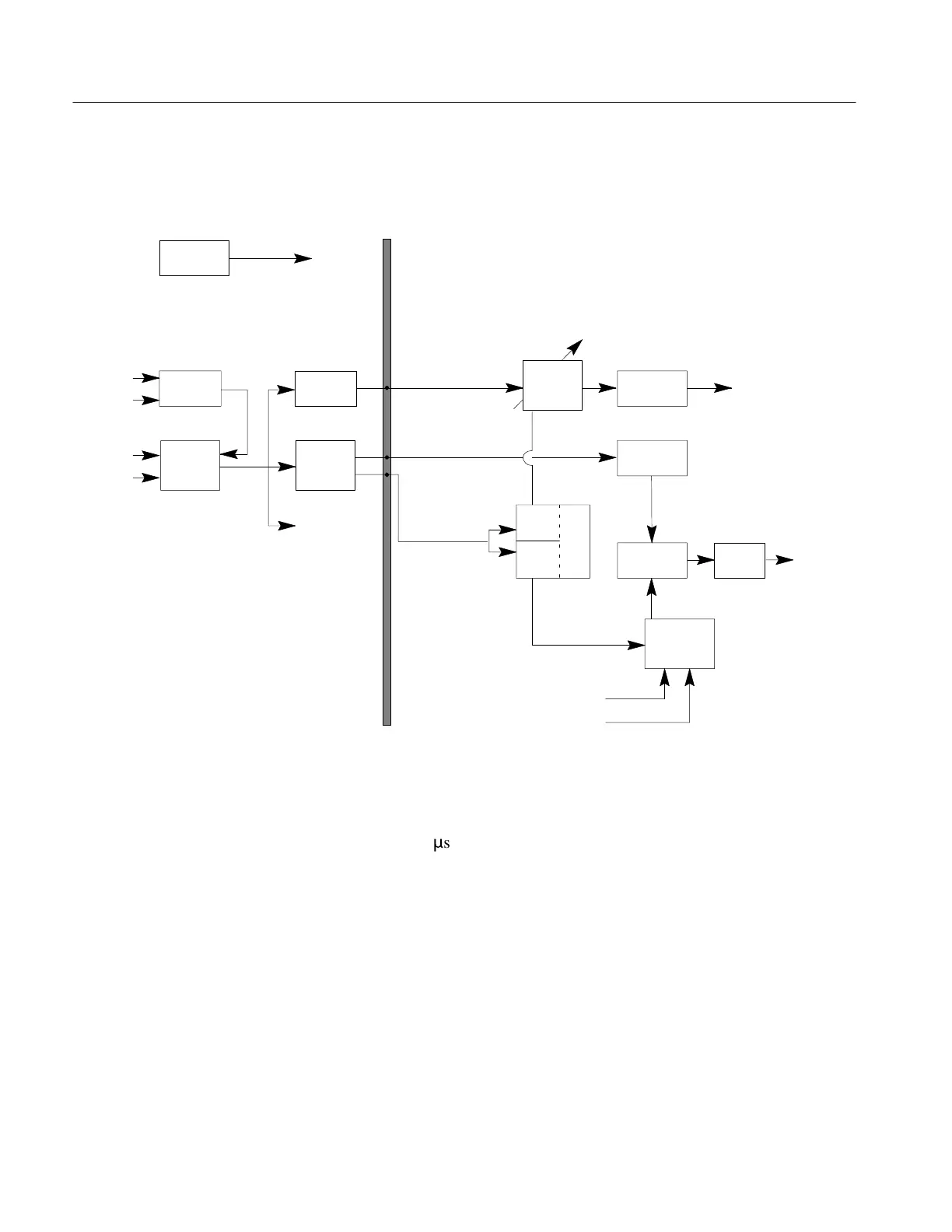
Figure 5–8: Timebase Block Diagram
A programmable digital counter, clocked at 2.5 MHz, is used to determine the PRT
(pulse repetition time) of the driver/sampler test pulse. The 1502C is programmed
with a PRT of 350
m
s. The output of the PRT counter is used to trigger a delay
counter, also clocked at 2.5 MHz, to provide coarse (400-ns resolution) digital time
delay. The end of this time delay triggers a fine delay counter, which is clocked at
20 MHz, providing 50-ns resolution to the sampler time delay. Both the coarse time
delay and the fine delay counters are programmed by the processor via the data bus.
The end of the coarse delay is used to generate a timebase interrupt request to the
processor to inform it that a sample is being taken and a timebase update is required
for the next sample.
The output of the fine delay counter is provided to the analog timebase circuits for
further delay control to become the sampler trigger. The beginning of the coarse
delay counter period is detected by a pulse former, which generates a driver trigger
for the analog timebase.
Artisan Technology Group - Quality Instrumentation ... Guaranteed | (888) 88-SOURCE | www.artisantg.com