Maintenance—2230 Service
5. Visual Check
WARHIHG
To avoid electrical shock, disconnect the Instrument
from the ac power source before making a visual
inspection of the internal circuitry.
Perform a visual inspection. This check may reveal bro
ken connections or wires, damaged components, semicon
ductors not firmly mounted, damaged circuit boards, or
other clues to the cause of an instrument malfunction.
6. Check Instrument Performance and Adjustment
Check the performance of either those circuits where
trouble appears to exist or the entire instrument. The
apparent trouble may be the result of misadjustment.
Complete performance check and adjustment instructions
are given in Sections 4 and 5 of this manual.
7. Isolate Trouble to a Circuit
To isolate problems to a particular area, use any symp
toms noticed to help locate the trouble. Refer to the
“ Diagnostics" discussion in this section as an aid in locat
ing a faulty circuit.
8. Check Power Supplies
WARHIHG
For safety reasons, an isolation transformer must be
connected whenever troubleshooting is done in the
Preregulator and Inverter Power Supply sections of
the instrument.
When trouble symptoms appear in more that one cir
cuit, first check the power supplies; then check the
affected circuits by taking voltage and waveform readings.
Check first for the correct output voltage of each individual
supply. These voltages are measured between the power
supply test points and ground (see the associated circuit
board illustration and Table 6-7).
Voltages levels may be measured either with a DMM or
with an oscilloscope. Voltage ripple amplitudes must be
measured using an oscilloscope. Before checking power-
supply circuitry, set the INTENSITY control to normal
brightness, the A and B SEC/DIV switch to 0.1 ms, the
HORIZONTAL MODE to B, the ON/OFF READOUT TOG
GLE to display the readout, the A TRIGGER Mode to P-P
AUTO, and set the VERTICAL MODE switch to CH 1.
When measuring ripple, use a IX probe having a bay
onet ground assembly (see Table 6-7) attached to the
probe tip to minimize stray pickup. Insert the bayonet
assembly signal tip into the first test point indicated in
Table 6-7, and touch the bayonet assembly ground tip to
the chassis near the test point. The ripple values listed are
based on a system limited in bandwidth to 30 kHz. Using a
system with wider bandwidth will result in higher readings.
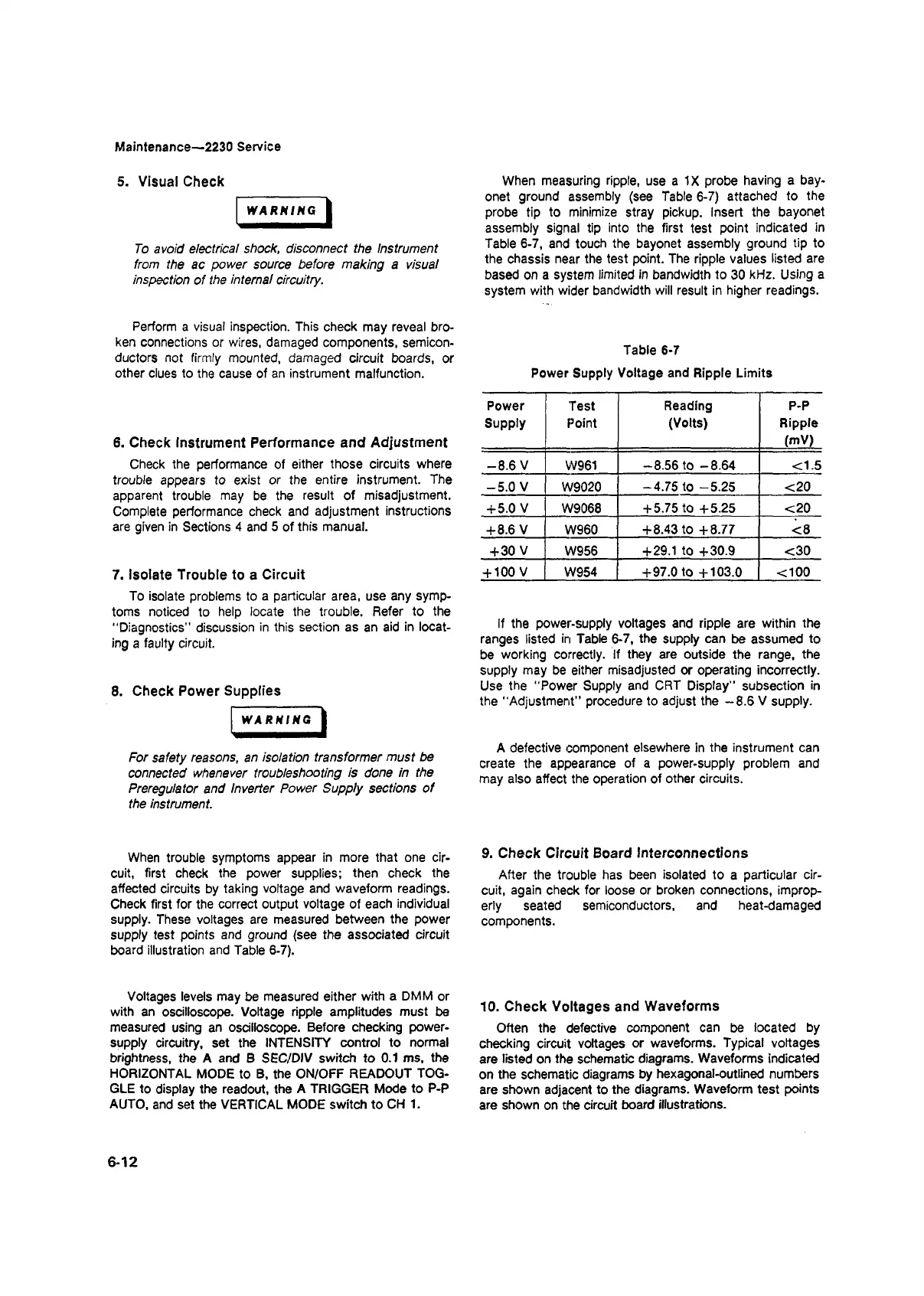
Table 6-7
Power Supply Voltage and Ripple Limits
Power
Supply
Test
Point
Reading
(Volts)
P-P
Ripple
(mV)
-8.6 V
W961
-8.56 to -8.64 <1.5
-5.0 V
W9020 -4.75 to -5.25
<20
+ 5.0 V
W9068
+ 5.75 to +5.25 <20
+8.6 V
W960
+8.43 to +8.77 <8
+30 V
W956
+29.1 to +30.9 <30
+ 100 V
W954 +97.0 to +103.0 <100
If the power-supply voltages and ripple are within the
ranges listed in Table 6-7, the supply can be assumed to
be working correctly. If they are outside the range, the
supply may be either misadjusted or operating incorrectly.
Use the “ Power Supply and CRT Display" subsection in
the “ Adjustment” procedure to adjust the —8.6 V supply.
A defective component elsewhere in the instrument can
create the appearance of a power-supply problem and
may also affect the operation of other circuits.
9. Check Circuit Board Interconnections
After the trouble has been isolated to a particular cir
cuit, again check for loose or broken connections, improp
erly seated semiconductors, and heat-damaged
components.
10. Check Voltages and Waveforms
Often the defective component can be located by
checking circuit voltages or waveforms. Typical voltages
are listed on the schematic diagrams. Waveforms indicated
on the schematic diagrams by hexagonal-outlined numbers
are shown adjacent to the diagrams. Waveform test points
are shown on the circuit board illustrations.
6-12