Performance Check Procedure—2230 Service
VERTICAL
Equipment Required (see Table 4-1):
Calibration Generator (Item 1)
Dual-Input Coupler (Item 9)
Leveled Sine-Wave Generator (Item 2)
50 0 BNC Termination (Item 12)
50 0 BNC Cable (Item 8)
10X Attenuator (Item 14)
INITIAL CONTROL SETTINGS PROCEDURE STEPS
Vertical (Both Channels)
POSITION
Midrange
VERTICAL MODE
CH 1
X-Y
Off (button out)
BW LIMIT
On (button in)
VOLTS/DIV
2 mV
VOLTS/DIV Variable
CAL detent
INVERT
Off (button out)
AC-GND-DC
DC
orizontal
POSITION Midrange
HORIZONTAL MODE
A
A SEC/DIV
20 /is
SEC/DIV Variable
CAL detent
X I0 Magnifier
Off (knob in)
Trigger
VAR HOLDOFF
NORM
Mode
P-P AUTO
SLOPE
OUT
LEVEL
Midrange
HF REJECT
OFF
A&B INT
VERT MODE
A SOURCE
INT
A EXT COUPLING
AC
torage
STORE/NON STORE
NON STORE (button out)
SAVE/CONTINUE
CONTINUE (button out)
PRETRIG/POST TRIG
POST TRIG (button out)
ROLLJSCAN
SCAN (button out)
1K/4K
4K (button out)
POSITION CURS/
POSITION CURS
SELECT WAVEFORM
(button in)
WAVEFORM
REFERENCE/
WAVEFORM REFERENCE
MENU SELECT
(button in)
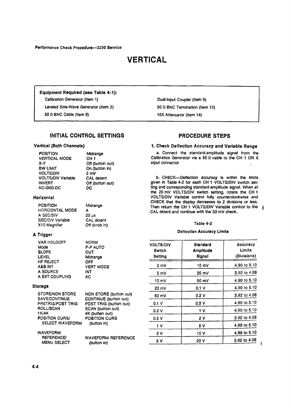
1. Check Deflection Accuracy and Variable Range
a. Connect the standard-amplitude signal from the
Calibration Generator via a 50 Q cable to the CH 1 OR X
input connector.
b. CHECK—Deflection accuracy is within the limits
given in Table 4-2 for each CH 1 VOLTS/DIV switch set
ting and corresponding standard-amplitude signal. When at
the 20 mV VOLTS/DIV switch setting, rotate the CH 1
VOLTS/DIV Variable control fully counterclockwise and
CHECK that the display decreases to 2 divisions or less.
Then return the CH 1 VOLTS/DIV Variable control to the |
CAL detent and continue with the 50 mV check.
Table 4-2
Deflection Accuracy Limits
VOLTS/DIV
Switch
Setting
Standard
Amplitude
Signal
Accuracy
Limits
(Divisions)
2 mV 10 mV
4.90 to 5.10
5 mV
20 mV
3.92 to 4.08
10 mV
50 mV
4.90 to 5.10
20 mV
0.1 V
4.90 to 5.10
50 mV
0.2 V
3.92 to 4.08
0.1 V
0.5 V
4.90 to 5.10
0.2 V 1 V
4.90 to 5.10
0.5 V
2 V
3.92 to 4.08
1 V
5 V
4.90 to 5.10
2 V 10 V
4.90 to 5.10
5 V 20 V
3.92 to 4.08
4-4