Options—2230 Service
(power failing), interrupts are generated to tell the
Microprocessor that instrument power is going down. A
LO FAIL is also delayed by U1132C, D, and associated cir
cuitry, making STANDBY LO. This places the RAM in the
low current standby operating mode.
PERFORMANCE CHECK
PROCEDURE
Introduction
This part of Section 7 contains the GPIB Option and
RS-232-C portion of the instrument’s performance check
procedures. The "Performance Check Procedure” is used
to check the GPIB Option performance against the
requirements listed in Table 7-4. It is not necessary to
remove the instrument cover to accomplish any of the per
formance checks.
The Option performance check intervals are identical to
the basic instrument as indicated in "Performance Check
Interval” in the "Performance Check Procedure" Section 4
of this manual.
Limits and Tolerances
The limits and tolerances stated in this procedure are
GPIB and RS-232-C specifications only if they are listed in
the "Performance Requirements” column of Table 7-4.
The tolerances given in this procedure are valid for an
instrument that is operating in and has been previously
calibrated in an ambient temperature between +20°C and
+30'C. The instrument also must have had at least a 20-
minute warm-up period. Refer to Table 7-4 for tolerances
applicable to an instrument that is operating outside this
temperature range. All tolerances specified are for the
instrument only and do not include test-equipment error.
When performing either the GPIB or the RS-232 checks, it
is assumed that the standard instrument meets all of its
"Performance Requirements” as stated in the
"Specification” (Section 1) of the Service manual.
Test Equipment Required
Test equipment listed in Table 7-37 is required to per
form this procedure. Test equipment specifications I
described in Table 7-37 are the minimum necessary to pro
vide accurate results. Therefore, equipment used must
meet or exceed the listed specifications. Detail operating
instructions for test equipment are not given in this pro
cedure.
When equipment other than that recommended is used,
control settings of the test setup may need to be altered.
If the exact item of equipment given as an example in
Table 7-37 is not available, check the "Minimum
Specification” column to determine if any other available
test equipment might suffice for the performance check
procedure.
1. GPIB Performance Check
a. Set the RS-232-C Parameter switch to match the
requirements of your controller, GPIB Address 1.
b. Set the oscilloscope's front panel controls to obtain
a baseline trace.
c. Set the oscilloscope’s POWER button to OFF and
then to ON.
d. CHECK—The SRQ indicator is on when the power-
up sequence is finished.
e. Connect the Controller via GPIB cable to the IEEE
STD 488 PORT connector.
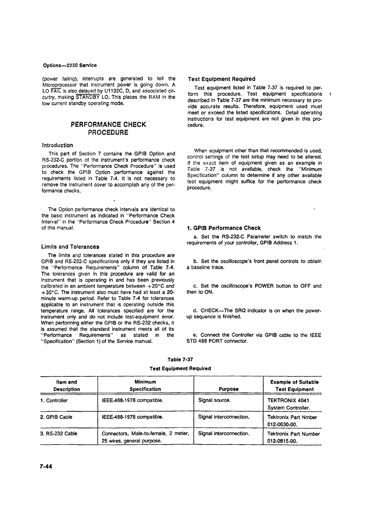
Table 7-37
Test Equipment Required
Item and
Description
Minimum
Specification Purpose
Example of Suitable
Test Equipment
1. Controller IEEE-488-1978 compatible.
Signal source.
TEKTRONIX 4041
System Controller.
2. GPIB Cable
IEEE-488-1978 compatible.
Signal interconnection.
Tektronix Part Nmber
012-0630-00.
3. RS-232 Cable
Connectors, Male-to-female, 2 meter,
25 wires, general purpose.
Signal interconnection.
Tektronix Part Number
012-0815-00.
7-44