Maintenance—2230 Service
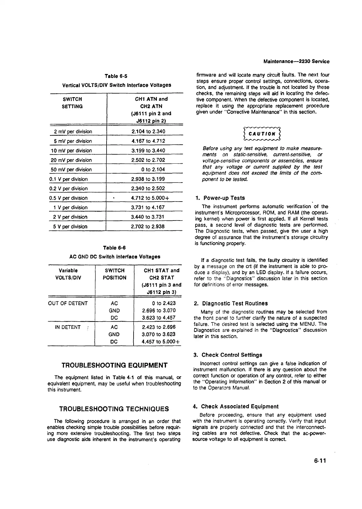
Table 6-5
Vertical VOLTS/DIV Switch Interface Voltages
SWITCH
SETTING
CHI ATN and
CH2 ATN
(J6111 pin 2 and
J6112 pin 2)
2 mV per division
2.104 to 2.340
5 mV per division
4.167 to 4.712
10 mV per division
3.199 to 3.440
20 mV per division
2.502 to 2.702
50 mV per division Oto 2.104
0.1 V per division 2.938 to 3.199
0.2 V per division 2.340 to 2.502
0.5 V per division 4.712 to 5.000+
1 V per division
3.731 to 4.167
2 V per division
3.440 to 3.731
5 V per division
2.702 to 2.938
Table 6-6
AC GND DC Switch Interface Voltages
Variable
VOLTS/DIV
SWITCH
POSITION
CHI STAT and
CH2 STAT
(J6111 pin 3 and
J6112 pin 3)
OUT OF DETENT
AC
0 to 2.423
GND
2.696 to 3.070
DC
3.623 to 4.457
IN DETENT ;
AC
2.423 to 2.696
GND 3.070 to 3.623
DC 4.457 to 5.000+
TROUBLESHOOTING EQUIPMENT
The equipment listed in Table 4-1 of this manual, or
equivalent equipment, may be useful when troubleshooting
this instrument.
TROUBLESHOOTING TECHNIQUES
The following procedure is arranged in an order that
enables checking simple trouble possibilities before requir
ing more extensive troubleshooting. The first two steps
use diagnostic aids inherent in the instrument’s operating
firmware and will locate many circuit faults. The next four
steps ensure proper control settings, connections, opera
tion, and adjustment. If the trouble is not located by these
checks, the remaining steps will aid in locating the defec
tive component. When the defective component is located,
replace it using the appropriate replacement procedure
given under "Corrective Maintenance" in this section.
) CAUTION <
Before using any lest equipment to make measure
ments on static-sensitive, current-sensitive, or
voltage-sensitive components or assemblies, ensure
that any voltage or current supplied by the test
equipment does not exceed the limits o f the com
ponent to be tested.
1. Power-up Tests
The instrument performs automatic verification of the
instrument’s Microprocessor, ROM, and RAM (the operat
ing kernel) when power is first applied. If all Kernel tests
pass, a second level of diagnostic tests are performed.
The Diagnostic tests, when passed, give the user a high
degree of assurance that the instrument’s storage circuitry
is functioning properly.
If a diagnostic test fails, the faulty circuitry is identified
by a message on the crt (if the instrument is able to pro
duce a display), and by an LED display. If a failure occurs,
refer to the "Diagnostics" discussion later in this section
for definitions of error messages.
2. Diagnostic Test Routines
Many of the diagnostic routines may be selected from
the front panel to further clarify the nature of a suspected
failure. The desired test is selected using the MENU. The
Diagnostics are explained in the "Diagnostics” discussion
later in this section.
3. Check Control Settings
Incorrect control settings can give a false indication of
instrument malfunction. If there is any question about the
correct function or operation of any control, refer to either
the "Operating Information” in Section 2 of this manual or
to the Operators Manual.
4. Check Associated Equipment
Before proceeding, ensure that any equipment used
with the instrument is operating correctly. Verify that input
signals are properly connected and that the interconnect
ing cables are not defective. Check that the ac-power-
source voltage to all equipment is correct.
6-11