2230 Service
LIST OF TABLES
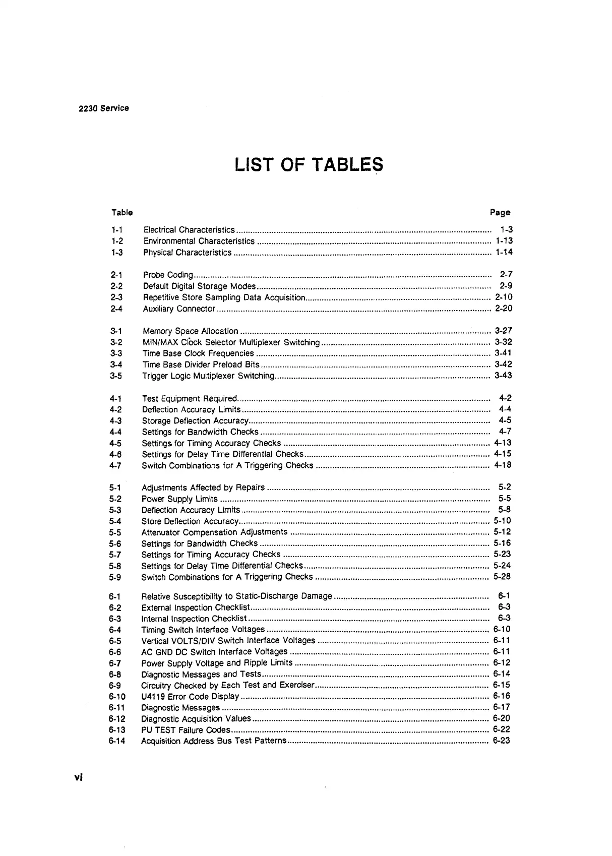
Table Page
1-1 Electrical Characteristics............................................................................................................. 1-3
1-2 Environmental Characteristics.................................................................................................... 1-13
1- 3 Physical Characteristics.............................................................................................................. 1-14
2- 1 Probe Coding............................................................................................................................... 2-7
2-2 Default Digital Storage Modes................................................................................................... 2-9
2-3 Repetitive Store Sampling Data Acquisition
.............................
2-10
2- 4 Auxiliary Connector..................................................................................................................... 2-20
3- 1 Memory Space Allocation
........................................................
1..........3-27
3-2 MIN/MAX Clock Selector Multiplexer Switching
........................................................................
3-32
3-3 Time Base Clock Frequencies.................................................................................................... 3-41
3-4 Time Base Divider Preload Bits.................................................................................................. 3-42
3- 5 Trigger Logic Multiplexer Switching............................................................................................ 3-43
4- 1 Test Equipment Required............................................................................................................ 4-2
4-2 Deflection Accuracy Limits.......................................................................................................... 4-4
4-3 Storage Deflection Accuracy
......................................................
4-5
4-4 Settings for Bandwidth Checks
..................................................
4-7
4-5 Settings for Timing Accuracy Checks..........................................................................................4-13
4-6 Settings for Delay Time Differential Checks............................................................................... 4-15
4- 7 Switch Combinations for A Triggering Checks.......................................................................... 4-18
5- 1 Adjustments Affected by Repairs
..............................................................................................
5-2
5-2 Power Supply Limits................................................................................................................... 5-5
5-3 Deflection Accuracy Limits......................................................................................................... 5-8
5-4 Store Deflection Accuracy.......................................................................................................... 5-10
5-5 Attenuator Compensation Adjustments
.....................................
5-12
5-6 Settings for Bandwidth Checks.................................................. 5-16
5-7 Settings for Timing Accuracy Checks........................................................................................ 5-23
5-8 Settings for Delay Time Differential Checks
..............................................................................
5-24
5- 9 Switch Combinations for A Triggering Checks.......................................................................... 5-28
6- 1 Relative Susceptibility to Static-Discharge Damage.................................................................. 6-1
6-2 External Inspection Checklist..................................................................................................... 6-3
6-3 Internal Inspection Checklist...................................................................................................... 6-3
6-4 Timing Switch Interface Voltages.............................................................................................. 6-10
6-5 Vertical VOLTS/DIV Switch Interface Voltages......................................................................... 6-11
6-6 AC GND DC Switch Interface Voltages.................................................................................... 6-11
6-7 Power Supply Voltage and Ripple Limits
..................................................................................
6-12
6-8 Diagnostic Messages and Tests.................................................................................................. 6-14
6-9 Circuitry Checked by Each Test and Exerciser.......................................................................... 6-15
6-10 U4119 Error Code Display......................................................................................................... 6-16
6-11 Diagnostic Messages................................................................... 6-17
6-12 Diagnostic Acquisition Values......................................................................................................6-20
6-13 PU TEST Failure Codes............................................................................................................... 6-22
6-14 Acquisition Address Bus Test Patterns..................................................................................... 6-23
vi