Performance Check Procedure—2230 Service
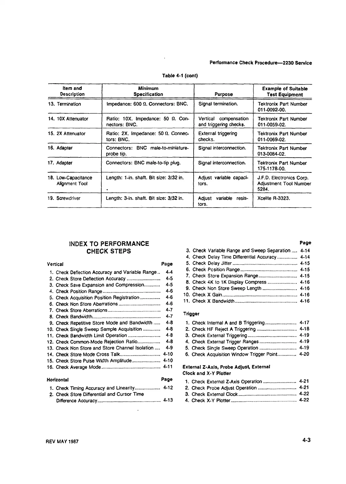
Table 4-1 (cont)
Item and
Description
Minimum
Specification
Purpose
Example of Suitable
Test Equipment
13. Termination Impedance: 600 9. Connectors: BNC.
Signal termination.
Tektronix Part Number
011-0092-00.
14. 10X Attenuator Ratio: 10X. Impedance: 50 9. Con
nectors: BNC.
Vertical compensation
and triggering checks.
Tektronix Part Number
011-0059-02.
15. 2X Attenuator
Ratio: 2X. Impedance: 50 9. Connec
tors: BNC.
External triggering
checks.
Tektronix Part Number
011-0069-02.
16. Adapter
Connectors: BNC male-to-miniature-
probe tip.
Signal interconnection.
Tektronix Part Number
013-0084-02.
17. Adapter Connectors: BNC male-to-tip plug.
Signal interconnection.
Tektronix Part Number
175-1178-00.
18. Low-Capacitance
Alignment Tool
Length: 1-in. shaft. Bit size: 3/32 in. Adjust variable capaci
tors.
J.F.D. Electronics Corp.
Adjustment Tool Number
5284.
19. Screwdriver Length: 3-in. shaft. Bit size: 3/32 in.
Adjust variable resis
tors.
Xcelite R-3323.
INDEX TO PERFORMANCE
CHECK STEPS
Vertical Page
1. Check Deflection Accuracy and Variable Range.. 4-4
2. Check Store Deflection Accuracy
........................
4-5
3. Check Save Expansion and Compression
...........
4-5
4. Check Position Range
...........................................
4-6
5. Check Acquisition Position Registration
..............
4-6
6. Check Non Store Aberrations
...............................
4-6
7. Check Store Aberrations
.......................................
4-7
8. Check Bandwidth
...................................................
4-7
9. Check Repetitive Store Mode and Bandwidth
....
4-8
10. Check Single Sweep Sample Acquisition
............
4-8
11. Check Bandwidth Limit Operation
..........
4-8
12. Check Common-Mode Rejection Ratio
.................
4-8
13. Check Non Store and Store Channel Isolation .... 4-9
14. Check Store Mode Cross Talk
..............................
4-10
15. Check Store Pulse Width Amplitude
.....................
4-10
16. Check Average Mode............................................ 4-11
Horizontal Page
1. Check Timing Accuracy and Linearity
...................
4-12
2. Check Store Differential and Cursor Time
Difference Accuracy
..............................................
4-13
Page
3. Check Variable Range and Sweep Separation .... 4-14
4. Check Delay Time Differential Accuracy
..............
4-14
5. Check Delay Jitter................................................ 4-15
6. Check Position Range.......................................... 4-15
7. Check Store Expansion Range
............................
4-15
8. Check 4K to IK Display Compress
.....................
4-16
9. Check Non Store Sweep Length
.........................
4-16
10. Check X Gain
.......................................................
4-16
11. Check X Bandwidth.............................................. 4-16
Trigger
1. Check Internal A and B Triggering
.......................
4-17
2. Check HF Reject A Triggering
.............................
4-18
3. Check External Triggering
....................................
4-19
4. Check External Trigger Ranges
...........................
4-19
5. Check Single Sweep Operation
...........................
4-19
6. Check Acquisition Window Trigger Point
.............
4-20
External Z-Axis, Probe Adjust, External
Clock and X-Y Plotter
1. Check External Z-Axis Operation
........................
4-21
2. Check Probe Adjust Operation
............................
4-21
3. Check External Clock........................................... 4-22
4. Check X-Y Plotter................................................. 4-22
REV MAY 1987
4-3