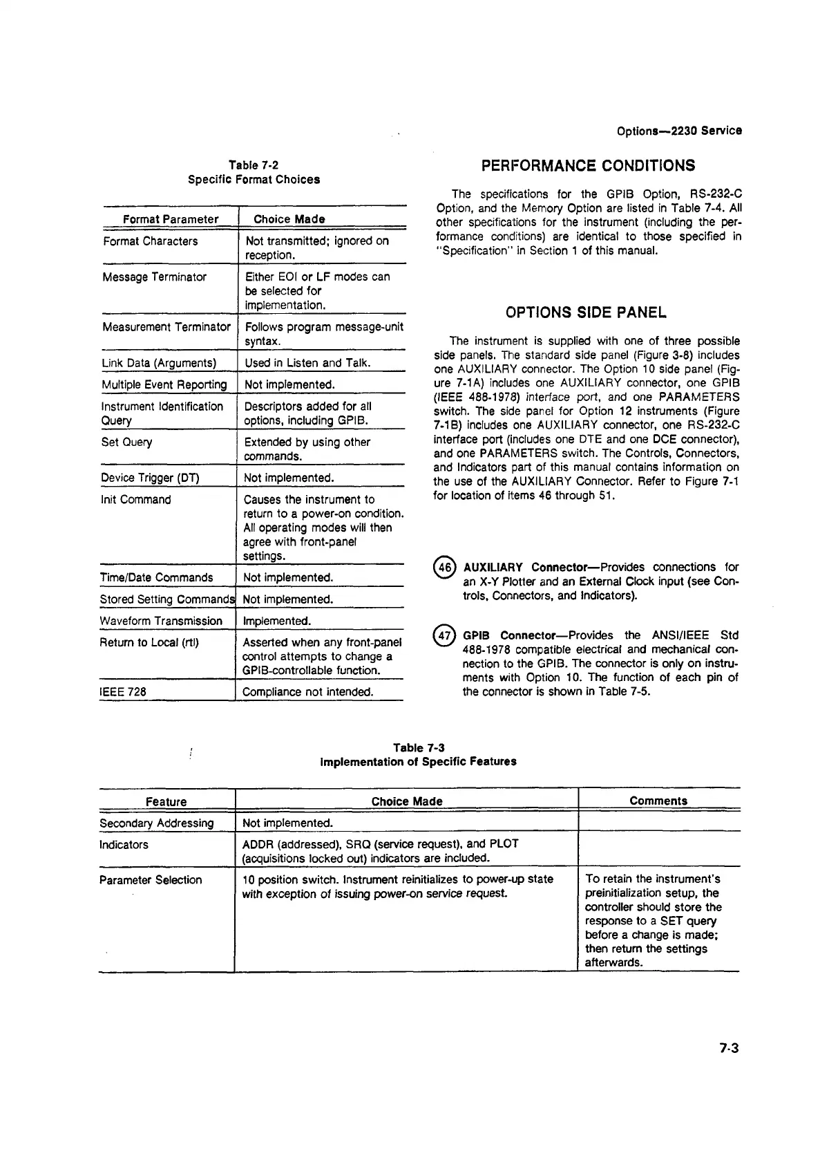
Table 7-2
Specific Format Choices
Options—2230 Service
PERFORMANCE CONDITIONS
Format Parameter Choice Made
Format Characters
Not transmitted; ignored on
reception.
Message Terminator Either EOI or LF modes can
be selected for
implementation.
Measurement Terminator Follows program message-unit
syntax.
Link Data (Arguments) Used in Listen and Talk.
Multiple Event Reporting Not implemented.
Instrument Identification
Query
Descriptors added for all
options, including GPIB.
Set Query
Extended by using other
commands.
Device Trigger (DT)
Not implemented.
Init Command Causes the instrument to
return to a power-on condition.
All operating modes will then
agree with front-panel
settings.
Time/Date Commands Not implemented.
Stored Setting Commands Not implemented.
Waveform Transmission Implemented.
Return to Local (rtl) Asserted when any front-panel
control attempts to change a
GPIB-controIlable function.
IEEE 728 Compliance not intended.
The specifications for the GPIB Option, RS-232-C
Option, and the Memory Option are listed in Table 7-4. All
other specifications for the instrument (including the per
formance conditions) are identical to those specified in
"Specification" in Section 1 of this manual.
OPTIONS SIDE PANEL
The instrument is supplied with one of three possible
side panels. The standard side panel (Figure 3-8) includes
one AUXILIARY connector. The Option 10 side panel (Fig
ure 7-1 A) includes one AUXILIARY connector, one GPIB
(IEEE 488-1978) interface port, and one PARAMETERS
switch. The side panel for Option 12 instruments (Figure
7-1B) includes one AUXILIARY connector, one RS-232-C
interface port (includes one DTE and one DOE connector),
and one PARAMETERS switch. The Controls, Connectors,
and Indicators part of this manual contains information on
the use of the AUXILIARY Connector. Refer to Figure 7-1
for location of items 46 through 51.
U 6) AUXILIARY Connector—Provides connections for
an X-Y Plotter and an External Clock input (see Con
trols, Connectors, and Indicators).
^ 7) GPIB Connector—Provides the ANSI/IEEE Std
488-1978 compatible electrical and mechanical con
nection to the GPIB. The connector is only on instru
ments with Option 10. The function of each pin of
the connector is shown in Table 7-5.
Table 7-3
Implementation of Specific Features
Feature
Choice Made
Comments
Secondary Addressing
Not implemented.
Indicators
ADDR (addressed), SRQ (service request), and PLOT
(acquisitions locked out) indicators are included.
Parameter Selection
10 position switch. Instrument reinitializes to power-up state
To retain the instrument's
with exception of issuing power-on service request.
preinitialization setup, the
controller should store the
response to a SET query
before a change is made;
then return the settings
afterwards.
7-3