For a Nonstore X-Y display CR818, CR817, and
CR816 are reverse biased. The XY signal is LO to reverse
bias CR551 and allow current in R820 to flow through
CR820. The crt intensity is then controlled by the A
INTENSITY potentiometer which sets the current in R820
through Q804.
Theory of Operation—2230 Service
During Nonstore operation, any applied External Z-Axis
input voltages drive proportional input currents through
R822 and R823 to the Z-Axis Amplifier. Sensitivity to
external signals is determined by the transresistance gain
of the shunt-feedback amplifier. Diode CR823 protects the
Z-Axis Amplifier if excessive voltage levels are applied to
the EXT Z AXIS INPUT connector. External Z-Axis modu
lation does not function for STORE MODE displays.
BEAM FIND switch S390 controls the base bias volt
ages of Q825 and Q829. When the BEAM FIND button is
out, -8.6 V is supplied to the normal base-biasing net
work. When the button is held in, the -8 .6 V supply is
removed, and the voltage at the anode of VR828 rises to
about -5.6 V. This voltage level turns off the current sup
ply from Q829. The Z-Axis amplifier output voltage is then
fixed by R835 and the voltage at the BEAM FIND switch,
as set by other parts of the Beam Find circuitry. The out
put voltage of Q835 is set to a level that displays either a
bright trace or dot (depending on whether the sweep is
triggered or not), and the INTENSITY controls and the Z-
Axis drive signals have no control over the crt intensity.
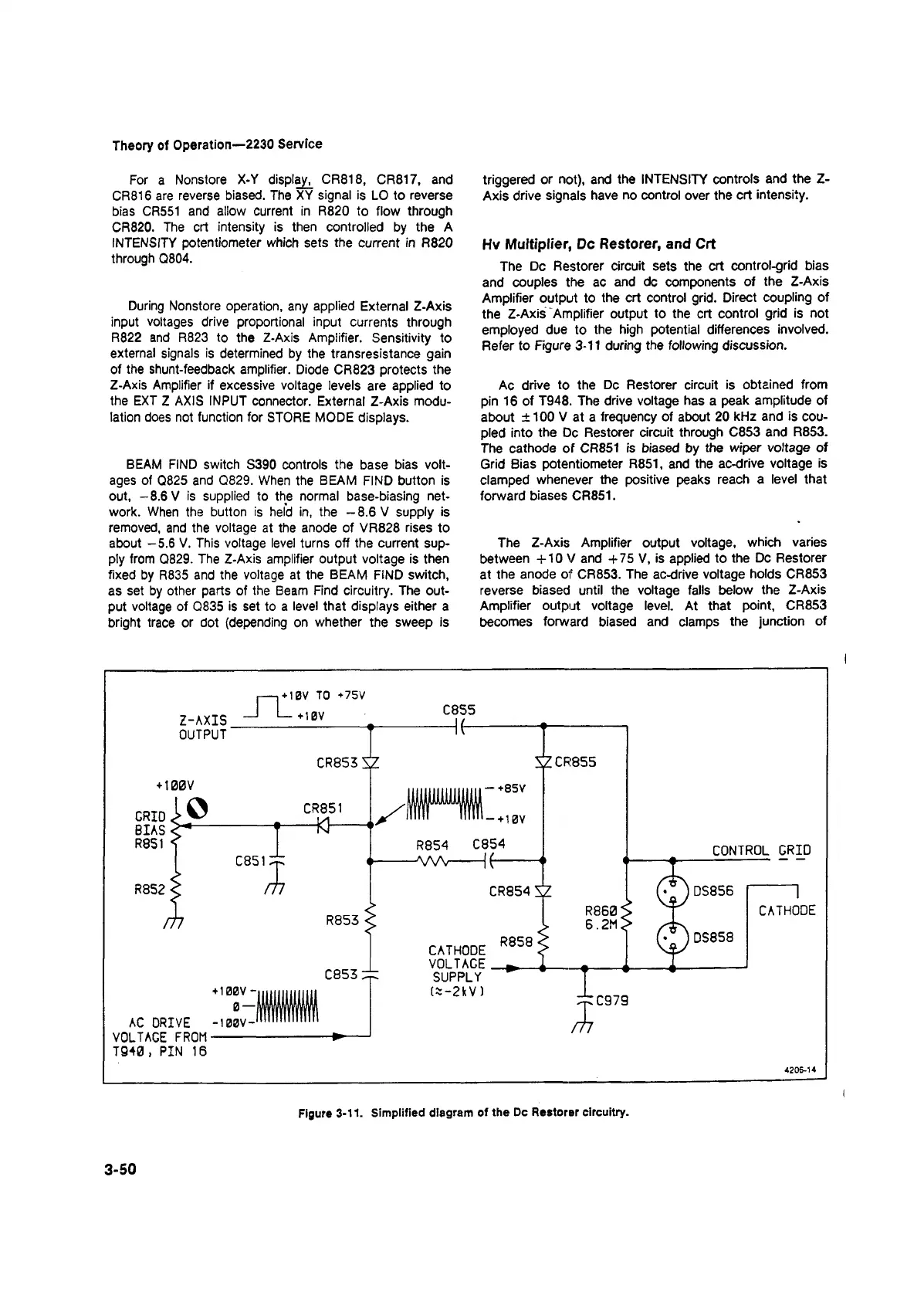
Hv Multiplier, Dc Restorer, and Crt
The Dc Restorer circuit sets the crt control-grid bias
and couples the ac and dc components of the Z-Axis
Amplifier output to the crt control grid. Direct coupling of
the Z-Axis Amplifier output to the crt control grid is not
employed due to the high potential differences involved.
Refer to Figure 3-11 during the following discussion.
Ac drive to the Dc Restorer circuit is obtained from
pin 16 of T948. The drive voltage has a peak amplitude of
about ±100 V at a frequency of about 20 kHz and is cou
pled into the Dc Restorer circuit through C853 and R853.
The cathode of CR851 is biased by the wiper voltage of
Grid Bias potentiometer R851, and the ac-drive voltage is
clamped whenever the positive peaks reach a level that
forward biases CR851.
The Z-Axis Amplifier output voltage, which varies
between +10 V and +75 V, is applied to the Dc Restorer
at the anode of CR853. The ac-drive voltage holds CR853
reverse biased until the voltage falls below the Z-Axis
Amplifier output voltage level. At that point, CR853
becomes forward biased and clamps the junction of
3-50
Figure 3-11. Simplified diagram of the Dc Restorer circuitry.