BG7 Black Generator module
BG7 module
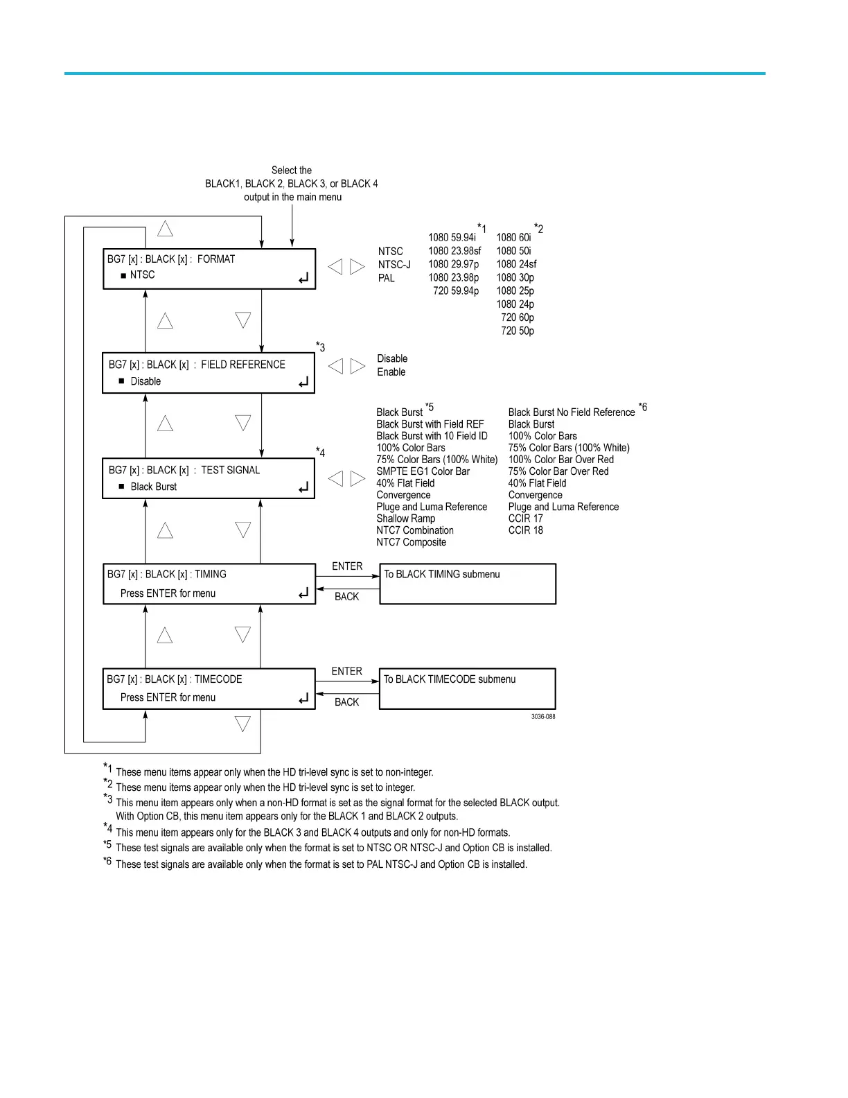
BLACK submenu
Use this menu to
set the signal format, timing, and timecode parameters for the
selected output. The following figure shows the BLACK submenu.
Figure 3-36: BG7 module BLACK submenu
3–66 TG8000 Multiformat Test Signal Generator User Manual

 Loading...


