DVG7 Digital Video Generator module
To select the test signal
All of the signa
l sets that are available in the module are already assigned to the
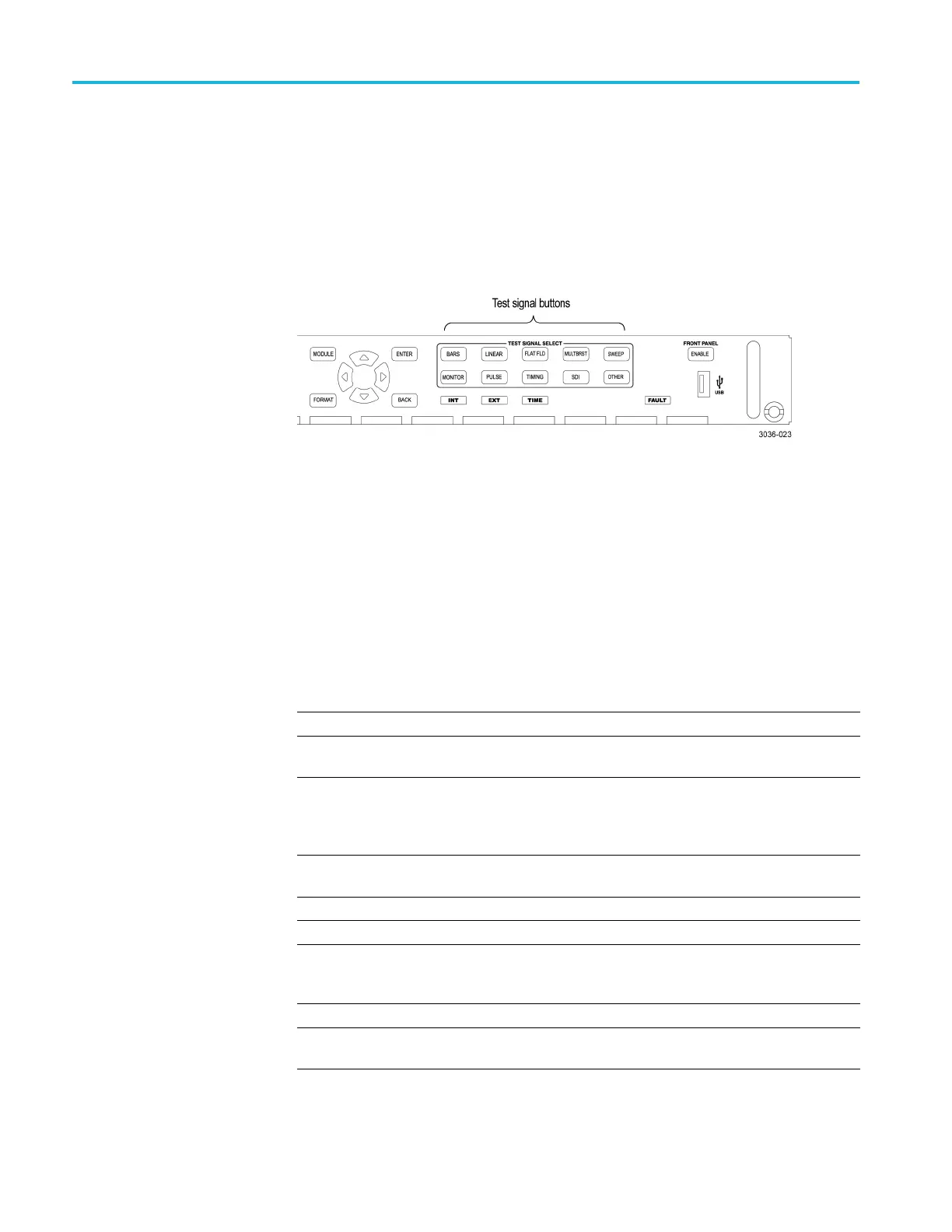
corresponding test signal buttons. When the DVG7 module is selected and you
press any of the front-panel test signal buttons, the selected signal in the signal set
is output. (See Figure 3-41.) For example, when you press the COLOR BAR test
signal button, a signal in the Color Bars signal set is output.
Use the left (◄)orright(►) arrow button, or press the COLOR BAR test signal
button repeatedly to select a different signal from the Color Bars signal set.
Figure 3-41: Front-panel test signal buttons
You can download a frame picture file (created by the Frame Picture Generator)
to the m ainframe and output the picture from the DVG7 module. Refer to the
TG8000 PC Tools Technical Reference for detailed information on how to create,
download, and output a f rame picture.
The following table lists the signal sets that are assigned to each test signal button
and shows the test signals that are available in each signal set. The list of available
signals changes depending on the selected signal format.
Table 3-17: DVG7 module signal set assigned to the test signal buttons
Button name Signal set Signals in the signal set
525-270 format
COLOR BAR Color Bars 100% Color Bars, 75% Color Bars, SMPTE Color
Bars
LINEARITY Linearity
10 Step, 3 Channel Ramp, 5 Step, B-Y Valid Ramp,
Limit Ramp, Modulated Ramp, Oversize Ramp,
R-Y Valid Ramp, Shallow Ramp, Shallow Ramp
Matrix, Valid Ramp, Y Valid Ramp
FLAT FIELD Flat Fields
0% Flat Field, 100% Flat Field, 50% Flat Field,
Field Square Wave
MULTI BURST
Multi Burst
60% Multiburst, Multipulse
SWEEP Sweep 100% Sweep, 60% Sweep, SinX/X
MONITOR
Monitor
2 Level Ped. & Pluge, 4 Level Ped. & Pluge,
Convergence Pattern, Gamut Test, Grey Window,
White Window
PULSE BAR Pulse & Bar
2T Pulse and Bar, T Pulses
TIMING
Timing 2.5 MHz Bowtie, 500 kHz Bowtie, Active Picture
Timing, Co-Siting Pulse
3–78 TG8000 Multiformat Test Signal Generator User Manual

 Loading...


