Operating basics
SDI7 module connectors
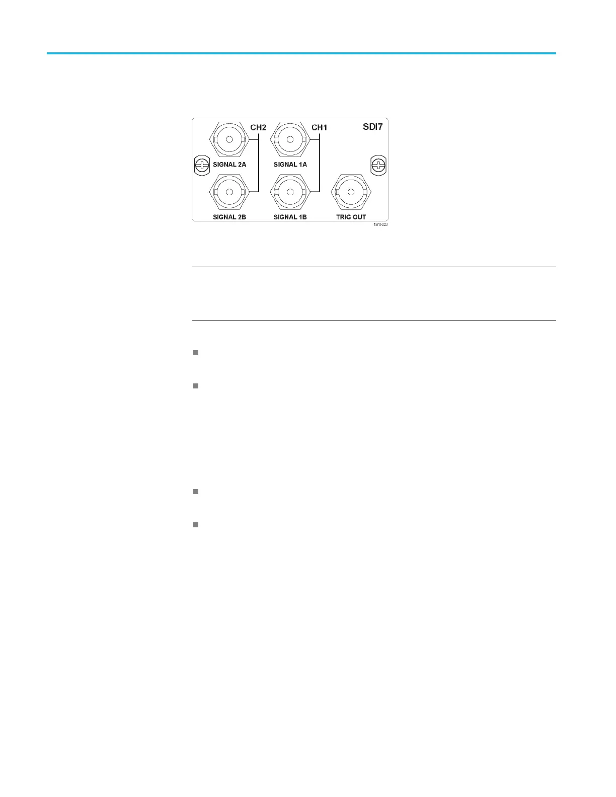
The SDI7 Dual Ch
annel SD/HD/3G SDI Video Generator module provides five
BNC connectors as described below. (See Figure 2-16.)
Figure 2-16: SDI7 module connectors
NOTE. Whe
n the SECONDARY O UTPUT selection is set to Test Pattern for
channel 1, the SIGNAL 1A and SIGNAL 1B connectors will output the same test
signal. The same is true for the channel 2 connectors when Test Pattern is set as
the SECONDARY OUTPUT selection for channel 2.
SIGNAL 1A: Outputs the selected SDI serial digital video te st signal for
channel 1.
SIGNAL 1B: This output can be configured to output one of the following
signals: Test Pattern, Black, Black (No Audio), Black (Mute Audio), Test
Pattern (No Audio), or Test Pattern (Mute Audio).
When set to any of the Test Pattern selections, the Signal 1A and Signal 1B
connectors will output the same test signal. When set to any of the Black
selections, the Signal 1B black signal is thesameformatandsamplestructure
as t
he Signal 1A output. (See page 3 -283, SDI7 module main menu.)
SIGNAL 2A: Outputs the selected SDI serial digital video te st signal for
ch
annel 2.
SIGNAL 2B: This output can be configured to output one of the following
si
gnals: Test Pattern, Black, Black (No Audio), Black (Mute Audio), Test
Pattern (No Audio), or Test Pattern (Mute Audio).
W
hen set to any of the Test Pattern selections, the Signal 2A and Signal 2B
connectors will output the same test signal. When set to any of the Black
selections, the Signal 2B black signal is thesameformatandsamplestructure
as the Signal 2A output.(See page 3-283, SDI7 module main menu.)
2–18 TG8000 Multiformat Test Signal Generator User Manual

 Loading...


