HD3G7 HD 3 Gb/s SDI Video Generator module
Sample Offset.
Use this menu selection to set the sample number where the
ancillary data header will be. This is the first word of the ancillary data packet.
Video Channel. Use this menu selection to set the video channel to Luma or
Chroma. Use the left (◄) and right (►) arrow buttons to make the selection, and
then press the ENTER buttontoconfirm it.
Link Location. Use this menu selection to set the link location to Link A or Link
B. Use the left (◄) a nd right (►) arrow buttons to make the selection, and then
press the ENTER button to confirm it. This menu selection is available only
in 3G-B formats.
Stream Lo
cation. Use the left (◄) and right (►) a rrow buttons to select HD
Stream 1 or HD Stream 2, and then press the ENT ER buttontoconfirm the
selection. This menu selection is available only in 2×HD formats.
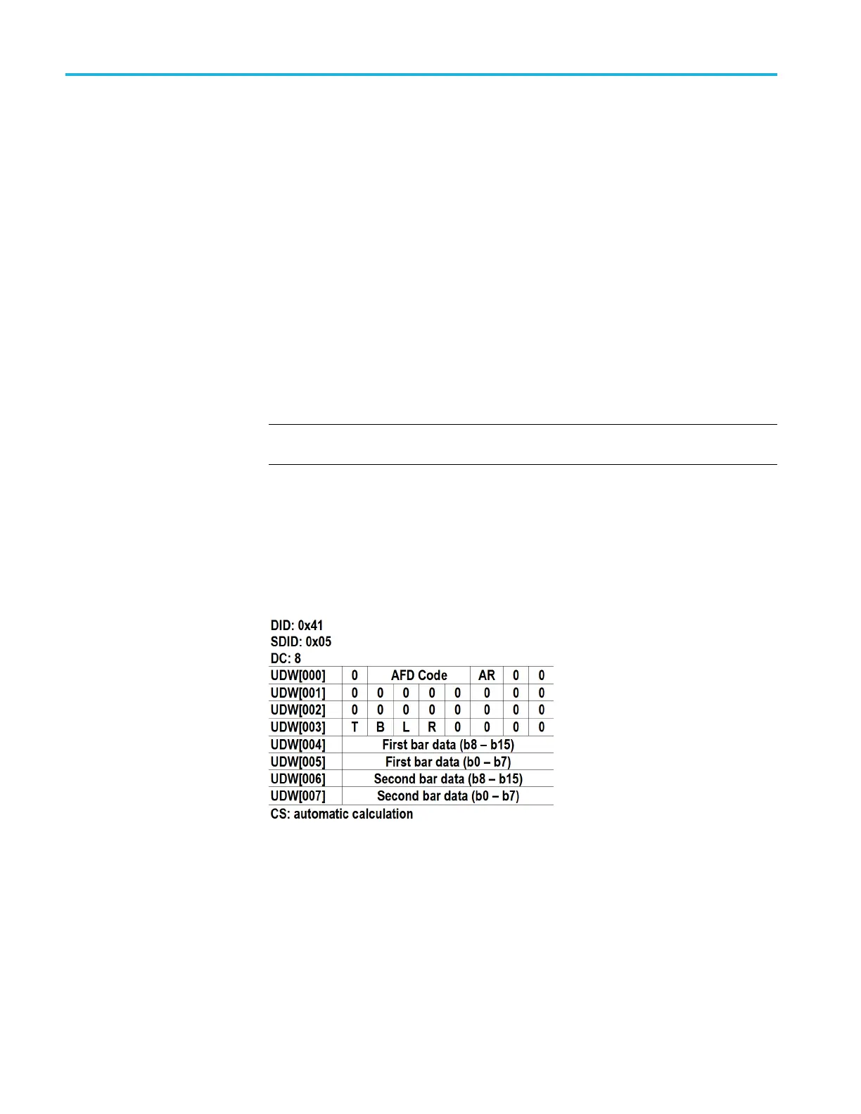
HD3G7 module ancillary
data payload example
NOTE. T
his is an example only. Inserting an AFD packet will not affect the video
produced by the HD3G7 module.
As an e
xample, one of the ancillary data payloads that can be easily generated by
the HD3G7 module is the Active Format Description (AFD). AFD is a method
of identifying the active area of the video picture to be displayed. Using AFD
the aspect ratio of the picture can be automatically optimized for the display
being used. AFD is defined in SMPTE 2016-1, and mapping AFD and bar data is
defined in SMPTE 2016-3. The packet format appears as shown here:
Where AR = aspect ratio (1=16:9, 0=4:3), T = top bar data flag, B= bottom bar
data flag, L = left bar data flag, and R = right bar data flag.
Note that these are all eight-bit values for the respective User Data Word. The
HD3G7 module will automatically calculate the parity bits when Parity is set to
Automatic, which is the default.
3–206 TG8000 Multiformat Test Signal Generator User Manual

 Loading...


