HDLG7 HD Dual Link Video Generator module
STATUS. Displa
ys the instrument operating mode, output signal format, and
output sample structure. Examples of the STATUS display are shown below for
each of the operating modes (converter and generator).
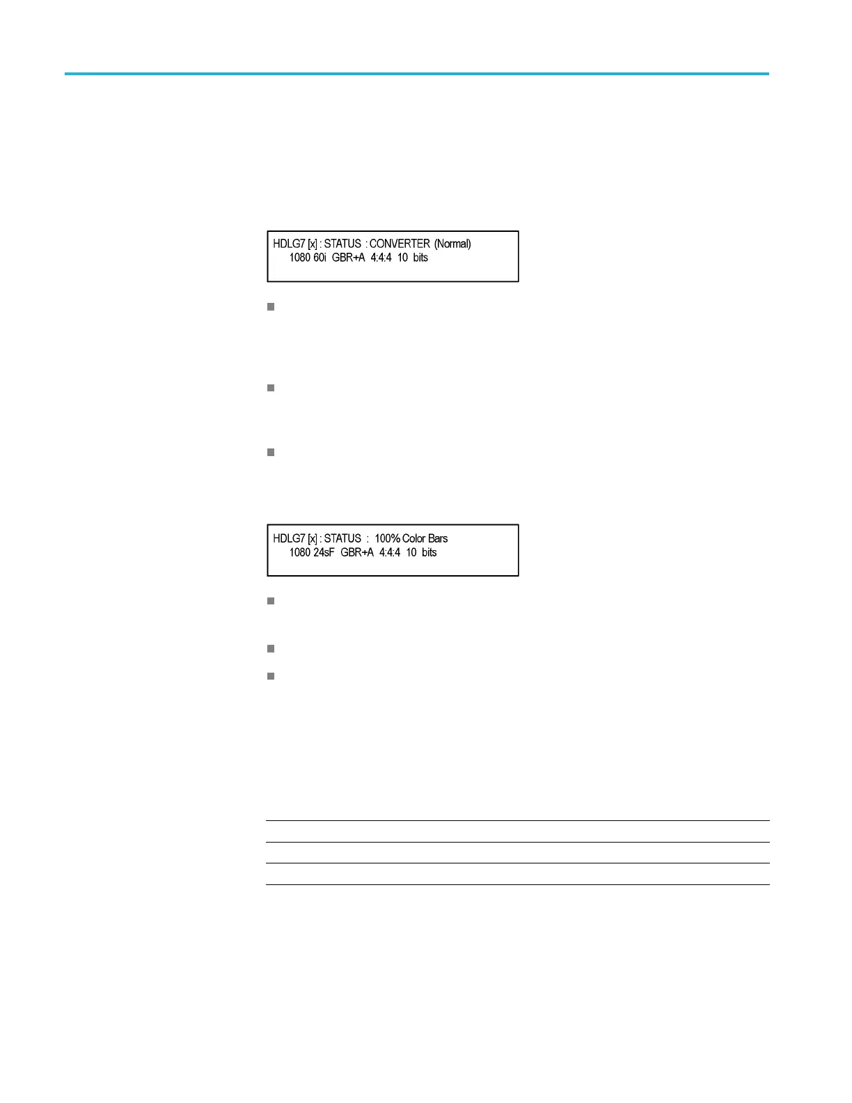
Converter Mode: The figure below shows an example STATUS display when
the module is in the converter m ode.
CONVERTER (Normal): Indicates that the incoming HD-SDI video stream
is being converted in a normal mode. The other choice is (Y to GBR) where
the incoming Y data is placed on the G, B, and R channels on the output. Y to
GBR is only selectable in the GBR sampling structure.
1080 60i: Indicates the incoming signal format. If there is no input or the
format is not the correct rate, the following messages will appear on the second
line of the LCD; "No Input Signal" or "Input Signal Error (Check FORMAT)"
GBR+A 4:4:4 10 bits: Indicates the output sampling structure.
Generator Mode: The figure below shows an example STATUS display when
the mo
dule is in the generator mode.
100
% Color Bars: Indicates the name of the signal currently being generated.
As different generator signal is selected, its name will be displayed.
108
0 24sF: Indicates the output format.
GBR+A 4:4:4 10 bits: Indicates the output sampling s tructure.
S
AMPLE STRUCTURE/DEPTH. Selects the sampling structure and pixel depth of
the output signal. Use the left (◄)orright(►) arrow button to select from the
formats listed in the table below. Press the ENTER button to confirm the selection.
Table 3-43: HDLG7 module sample structure/depth signal formats
1920 × 1080 formats
1080 GBR 4:4:4 12 bits 1080 GBR 4:4:4 10 bits 1080 GBR+A 4 :4:4 10 bits
1080 YCbCr 4:4:4 12 bits 1080 YCbCr 4:4:4 10 bits 1080 YCbCr+A 4:4:4 10 bits
1080 YCbCr 4:2:2 12 bits 1080 YCbCr 4:2:2 10 bits 1080 YCbCr+A 4:2:2 12 bits
3–224 TG8000 Multiformat Test Signal Generator User Manual

 Loading...


