Versa User Manual www.teledynetekmar.com
ELECTRONIC CONNECTIONS
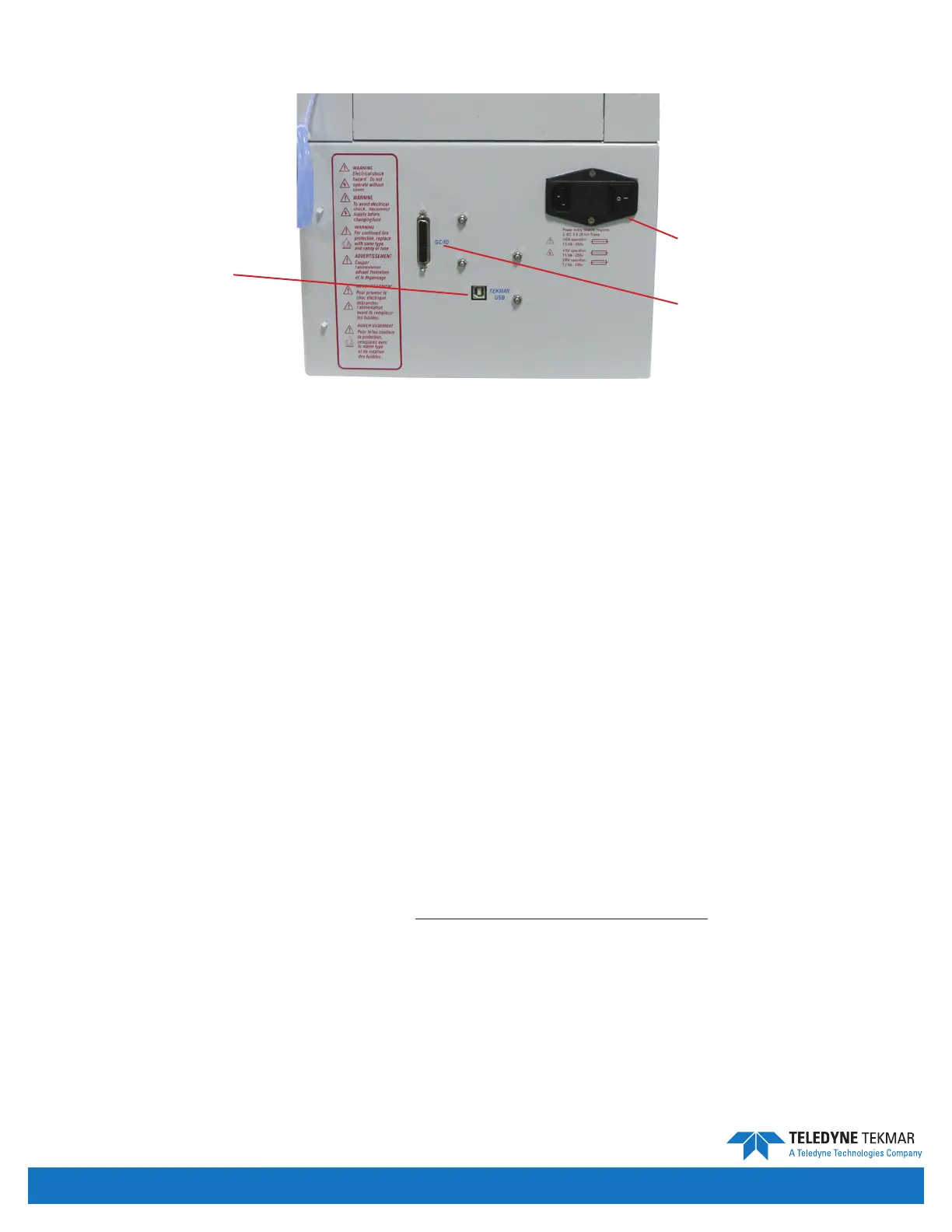
Power Entry Module
The power entry module is the black component on the right in gure above. There is a switch to turn the unit on and
o, a port for a power cord, and a fuse compartment.
USB Connection
The USB connection is used for interfacing a PC with the Versa unit.
GC/IO Interface
The GC/IO Interface is a 25-pin connection for interfacing the Versa with a GC.
CIRCUIT BOARDS
The printed circuit boards provide various voltages, receive and transmit signals, store programs, allow communication
with the instrument, and monitor time, temperature and pressure.
• Master Board
• Temperature Control Board
• GC/IO Board
• Elevator Motor Board
• Carousel Motor Board
• 24V DC Power Supply
• 5V DC Power Supply
• Pressure Transducer Board
Refer to circuit board pictures and diagrams in the Preventive Maintenance & Troubleshooting section should you need
to replace a board or cable.
Figure 1-17: Rear of Versa
USB Connection
Power Entry Module
GC/IO Interface
Introduction • Page 1-13


 To Next Page