Versa User Manual www.teledynetekmar.com
PRINTED CIRCUIT BOARDS
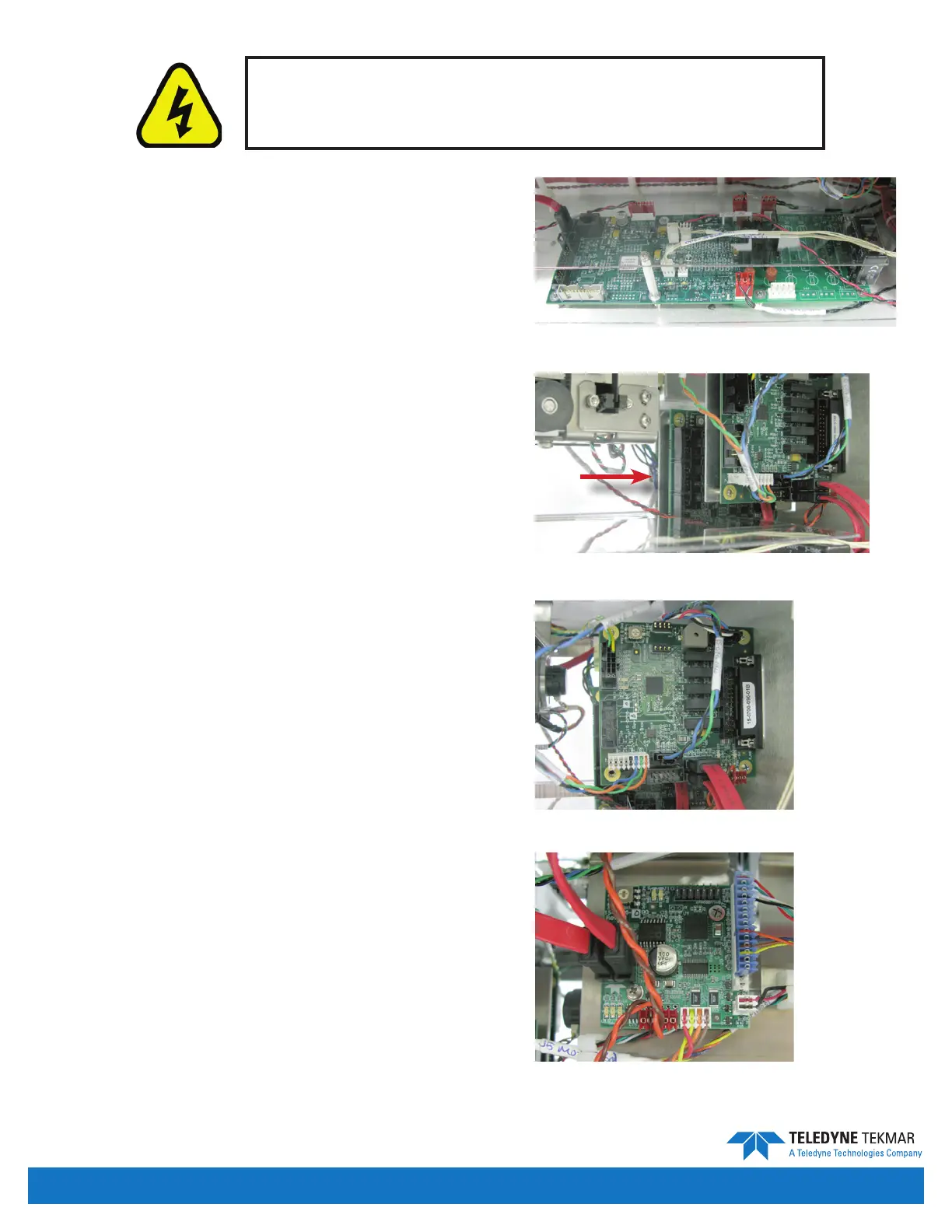
Versa operations are controlled by ve printed circuit
boards and two power supplies.
Temperature Control Board
The Temperature Board is on the bottom of the chassis on
the right-hand side. The Temperature Board is responsible
for all RTD feedback and temperature controls for the
standard heated zones.
Master Board
The Master Board is located on the right side of the back
panel, behind the GC/IO board. The Master Board is
responsible for all communication with the PC interface
as well as control for all motor movement. This board
has a cable that runs to the back of the unit for
communicating with the PC. The switch setting should
be set to position “zero.”
GC/IO Board
The GC/IO Board is located on the right side of the back
panel. The GC/IO Board is responsible for GC connection,
communication with all valves, the LED light, and other
boards. The switch setting should be set to position “zero.”
Elevator Motor Board
The Elevator Board is located on the elevator mechanism
and can be seen on the left side of the unit. The Elevator
Board is responsible for communication with the elevator
motor, optical sensors, encoder, mixer motor and other
boards. The switch setting should be set to position “zero.”
The interior of the instrument is an electrical shock hazard.
Turn o the instrument and unplug the power cord before
removing the protective covers.
Maintenance & Troubleshooting • Page 7-8
Figure 7-15: Temperature Control Board
Figure 7-16: Master Board
Figure 7-17: GC/IO Board
Figure 7-18: Elevator Motor Board


 To Next Page