Versa User Manual www.teledynetekmar.com
If any parts are missing, if you wish to order replacement parts, need technical support, or want an instrument
serviced, call the Teledyne Tekmar Customer Support Center at the number below:
U.S.A.: (800) 874-2004
Outside the U.S.A.: Country Code + 1 (513) 229-7000
Service Contact Information
Routine Procedures
LEAK CHECK
After everything is installed, but before running a sample, you
will need to run a Leak Check on your system.
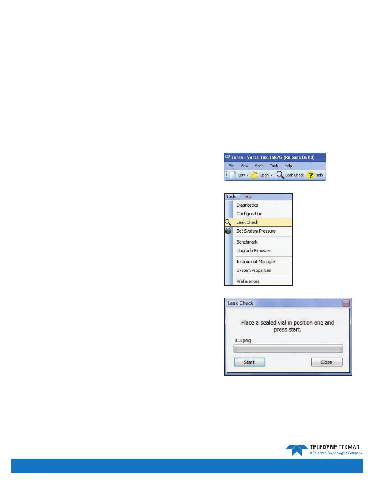
1. After starting Versa TekLink™2G, initiate the automatic
leak checking sequence from the main screen by clicking
on the Leak Check icon in the icon toolbar, or by going to
Tools | Leak Check.
2. After making the leak check selection, the unit will go from
System Ready to Leak Check. The Leak Check procedure is an
interactive process requiring the user to insert a fresh, tightly
capped headspace vial into position 1 of the carousel.
• User prompts and leak check results are updated in the
pop-up dialog boxes. The user will be required to monitor
the dialog boxes for direction and guidance through the
leak check procedure. The leak check results are recorded
in the sample history log for future reference.
• If the system fails the leak check, the user will need to
isolate the system leak and correct the problem. This is
important in order for the system to run under optimal
conditions, as well as to maintain leak tight conditions
within the GC injection port.
Items to Check for Leaks
1. Check the connection at the GC injection port.
2. Check the Valco ttings around the 6-port sample valve.
3. Check the nuts on the stainless steel tee inside the valve oven.
4. Check the Silcosteel 1/16” line entering the sample needle.
5. Check all ttings on the Solenoid Valves.
6. Check all ttings on the System Pressure Regulator.
7. Check the brass tee inside the chassis outside the oven,
100mL ow restrictor and the pressure transducer
connections.
8. Check gas supply and ttings.
Figure 7-3: Leak Check Screen
Figure 7-2: Tools Menu
Figure 7-1: Icon Bar
Maintenance & Troubleshooting • Page 7-1


 To Next Page