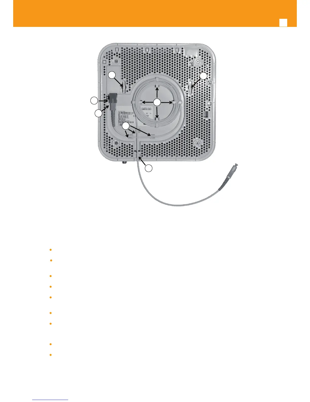
Figure 4-4: Refs. 769501-769502 back side –optical patch cord installation
Horizontal position
Remove the Refs. 769501-769502 optical adaptor protection cap, Figure 4-4- b);
Clean the Refs. 769501-769502 optical connector face within the optical adaptor with an appropriate optical connector cleaning
material;
Remove the protection cap of one of optical SC/APC connector of optical patchcord;;
Clean the optical SC/APC connector face with an appropriate optical connector cleaning material;
Plug the patchcord cleaned SC/APC optical connector on the Refs. 769501-769502 SC/APC adaptor, observing the alignment
mechanism, Figure 4-4- c);
You will hear a click when the connector is secure into place;
Pass the optical patchcord, in a counter- clockwise direction, round the storage circular guide on the back of the equipment, wrap-
ping it round as many times as necessary, Figure 4-4- d). Please avoid small bend radius on the patchcord (30mm minimum bend
radius);
Pass the other end of the optical patchcord to the outside of the equipment using the passing hole, Figure 4-4- f);
Fix the optical patchcord with plastic clamps to the Refs. 769501-769502 the appropriate xing support fastening the plastic clamp
just enough to secure the optical patchcord, Figure 4-4-e).