TEMPTRONIC
COEPSRATlGb2
Rev
A:
0611
5/98
Routine Maintenance
TP04100A
Interface
&
Applications
6.
Insert the Main Air thermocouple plug which you just disconnected into the female connector of the
Monitor "Y", thus connecting the Monitor to the System in series (use connector "B" on Figure 5-4).
Be aware of the plug's pin polarity (do not force the wide pin into the narrow slot).
7.
Connect the male Monitor
"Y"
plug into the Main Air thermocouple receptacle on the rear panel,
again taking care to match pin polarity (use connector "A" on Figure 5-4).
8.
On the user interface, press the "Esc" Program Button, which clears the Overheat Error.
9.
Access the
Define Parameters Screen
(see Item 1, above) and confirm these settings: DUT control
=
"Off," and DUT sensor
=
"Off.."
10. Then set the System temperature setpoint to
-10.0
OC and allow the System to run until a stable AT
TEMPERATURE is indicated within +1 "C of setpoint.
1
1. Read the Monitor (not the System AT TEMPERATURE) and record the Monitor value in Table 5-2.
12. If the difference between the Monitor and System readings is greater than +1 "C, then
recalibrate the
System
as
given in Section
0,
"Calibration," after restoring the System as follows in Item 13. Note:
Main Air High Temperature verification is
not required
as the Calibration procedure will
automatically recalibrate both Low and High Temperatures. If the difference between Monitor and
system readings is less than
+1
OC, skip to Item 14 below.
13. To restore the System,
turn
off main air flow; next disconnect the Monitor
"Y"
connectors; doing this
generates an "Overheat Error" on the display screen; reconnect the Main Air thermocouple plug into
the Main Air thermocouple receptacle (labeled MA TC) on the rear panel and clear
the
"Overheat
Error" from the screen.
14. If the difference between the Monitor and System readings is between (within the range of) +1 "C,
then proceed directly to Section 5-9.1.2.1, "Verify Main Air Mode (High Temperature)" on page 5-
17, and begin at Item 10, "Set System temperature to
+200.0
"C..." or continue Low Temperature
verification with the DUT Modes (T or
K)
below, and then proceed to High Temperature
Verification.
5-9.1.1.2
Verify
DUT T or DUT
K
Modes
(Low
Temperature)
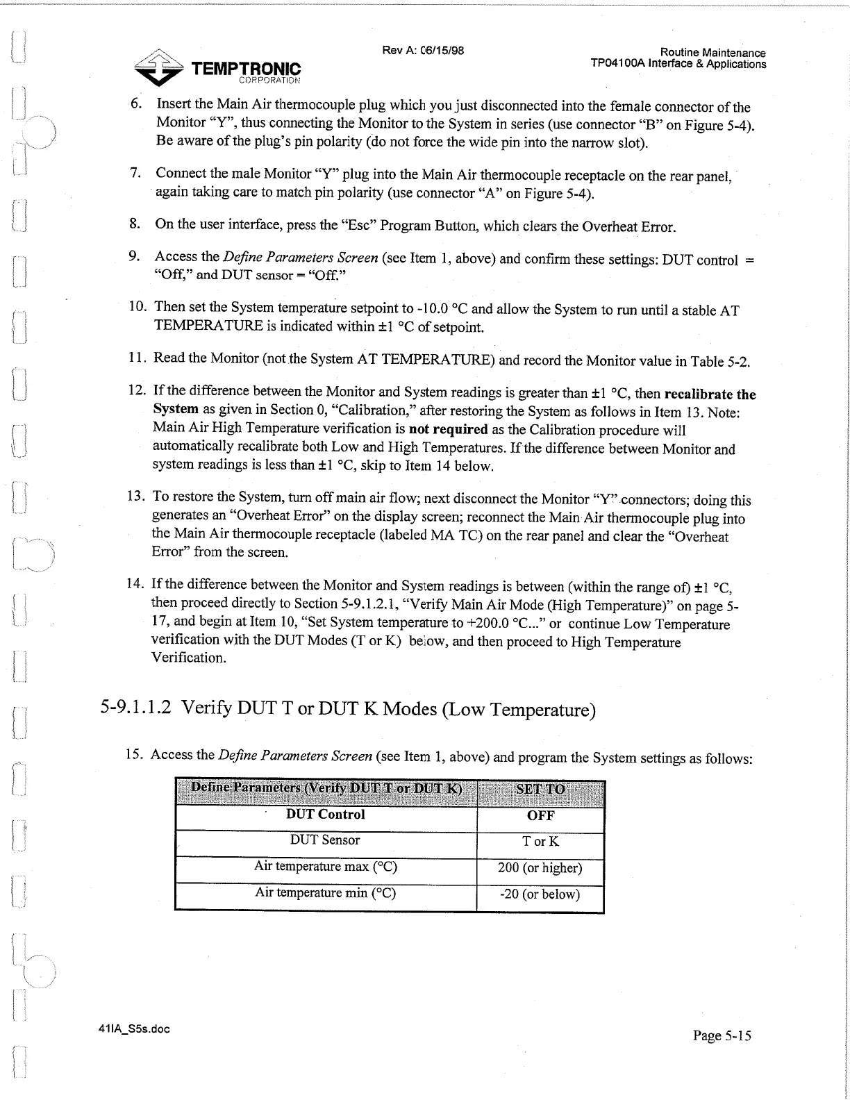
15. Access the
Define Parameters Screen
(see Item 1, above) and program the System settings as follows:
I
DUT
Sensor Tor
K
I
I
t
Air
temperature
max
("C)
1
200 (or higher)
I
I
Air temperature
min
("C)
1
-20 (or below)
Page 5-15
Artisan Technology Group - Quality Instrumentation ... Guaranteed | (888) 88-SOURCE | www.artisantg.com
 Loading...