,,&
Rev
A: 0611
5/98
A
TEMPTRONIC
v
COFPORiTlON
Preparation for
Use
TP04100A Interface
&
Applications
3.
Take the Thermal Wand Clamp (which contains Detent Inserts inside the clamp circumference, so
that the inside circumference is not round but is an oval shape) and slide it over the Horizontal Arm,
tighten the Horizontal Arm Lock
B
clamp, replace the cap on that end.
4.
Insert the Thermal Wand inside the Thermal Wand Clamp, seating it within the Detent Inserts, then
tighten the Thermal Wand Lock.
To "Manually Position The Thermal Head," see Section Three.
2-1
1.3
Install Insulation/Heat Shield
This assembly was designed to be both an insulator and a heat shield for the TP04100A ThermoWand.
As
an
insulator,
this assembly prevents water from condensing andlor frosting on the surface of the
ThermoWand during extended low temperature testing.
As a
heat shield,
this assembly protects
the
user's hand from being exposed to high temperature air flow.
This exposure is only a risk when the ThermoWand is being used as a hand held device AND a Thermal
Shroud is being utilized without
a
Thermal Cap.
In applications where a Thermal Cap is being used and no low temperature testing is being conducted for any
EXTENDED time periods, the Insulation/Heat Shield assembly may not be necessary.
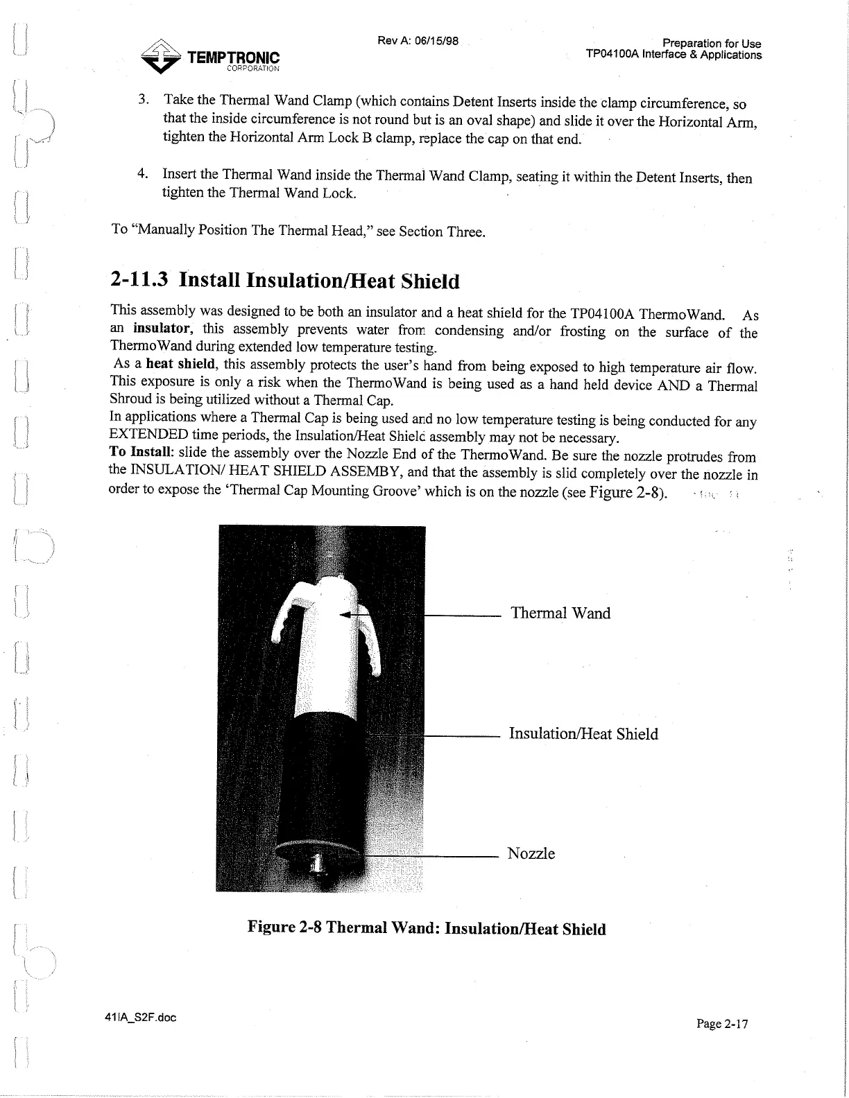
To
Install:
slide the assembly over the Nozzle End of the ThermoWand.
Be
sure the nozzle protrudes from
the INSULATION1 HEAT SHIELD ASSEMBY, and that the assembly is slid completely over the nozzle in
order to expose the 'Thermal Cap Mounting Groove' which is on the nozzle (see
Figure
2-8).
Thermal
Wand
Insulation/Heat
Shield
Nozzle
Figure
2-8
Thermal Wand: Insulation/Heat Shield
Page
2-17
Artisan Technology Group - Quality Instrumentation ... Guaranteed | (888) 88-SOURCE | www.artisantg.com
 Loading...