r
2
i
k
i
j
i
1
t
I
j
i
i,
i
i
I
%
1;
!
.,
,
.
1
i
I
i
!
j
I
I
I..
,.4:,
,
.
TEMPTRONIC
CCRPORPilrJI'I
Rev
A:
0611
5/98
2-6
Placement Requirements
2-6.1
Site and Clearances
Preparation
for
Use
TP04100A Interface
&
Applications
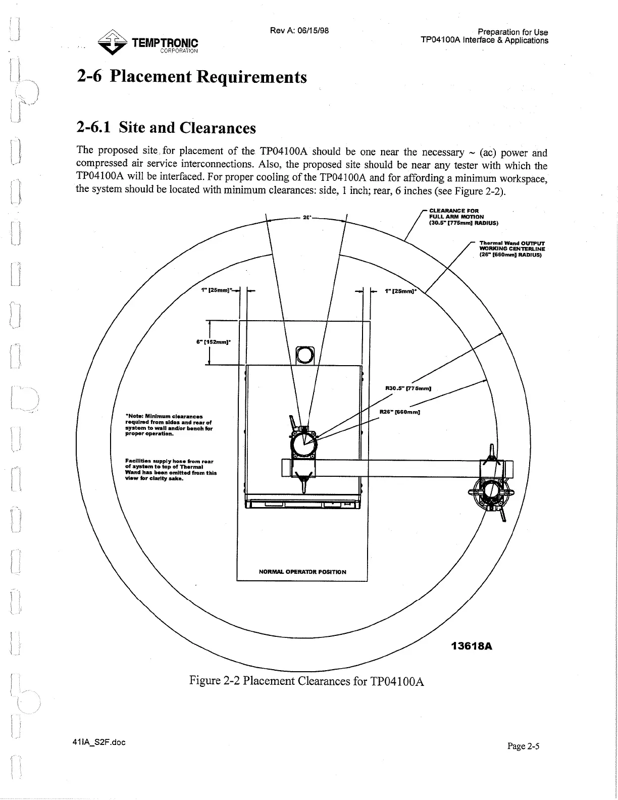
The proposed site for placement of the TP04100A should be one near the necessary
-
(ac) power and
compressed air service interconnections. Also, the proposed site should be near any tester with which the
TP04100A will be interfaced. For proper cooling of the TP04100A and for affording a minimum workspace,
the system should be located with minimum clearances: side, 1 inch; rear,
6
inches (see Figure
2-2).
.Noh Minimum clearances
requimd from sides and mar
of
system to
mil
andlor bench for
proper operation.
CLEARANCE FOR
20' FULL
ARM
MOTION
(30.6" t775mml RADIUS)
Thermal
Wand
OUTPUT
WORKING
CENTERLINE
(2V t660nunl RADIUS)
Facilities supply hose from rear
of Syrtom to top of Thermal
Wand
has
been omitted
from
this
view for clulty wke.
NORW OPEMTOR POSITION
Figure
2-2
Placement Clearances
for
TP04100A
Page
2-5
Artisan Technology Group - Quality Instrumentation ... Guaranteed | (888) 88-SOURCE | www.artisantg.com
 Loading...