Timer1
Timer3
Timer3 Ch1Output
Timer1 Ch1Output
Timer 3Ch0Compare
AND
Gate
IROUT
B0358-01
Timer3 Output
Timer1 Output
IROut
Start Timers
Timer3Ch1Compare
Timer3Ch0Compare
Timer1Ch1Compare
T0440-01
IR Signal Generation and Learning
www.ti.com
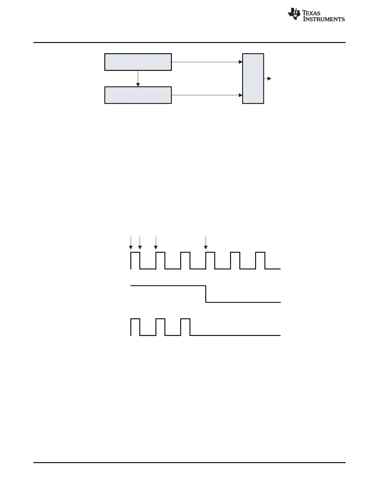
Figure 9-7. Block Diagram of Timers in IR-Generation Mode
The timing of the Timer 3 channel 1 output and Timer 1 channel 1 output signals is synchronized such that
no glitches are produced on the IR Out signal.
When the IRGEN bit is set, the IR out signal is routed to pins instead of the normal Timer 1 channel 1
output (see also Section 7.6.1).
Figure 9-8 shows the example of Timer 3 being initialized to a 33% duty cycle (T3CC0 = 3 × T3CC1).
Timer 1 has been initialized to 3.
Figure 9-8. Modulated Waveform Example
To achieve a period of space only, T1CC1 should be set to 0x00.
9.9.3 Non-Modulated Codes
To generate non-modulated IR codes, Timer 1 is used in modulo mode. The period of the signal is given
by T1CC0, and the pulse duration is given by T1CC1. T1CC1 gives the length of the mark period, and
T1CC0 gives the total number of mark and space periods. The compare values are buffered until the timer
hits 0x0000. The compare values must be updated once every period by the DMA or CPU if they are not
to be kept the same.
116
Timer 1 (16-Bit Timer) SWRU191C–April 2009–Revised January 2012
Submit Documentation Feedback
Copyright © 2009–2012, Texas Instruments Incorporated