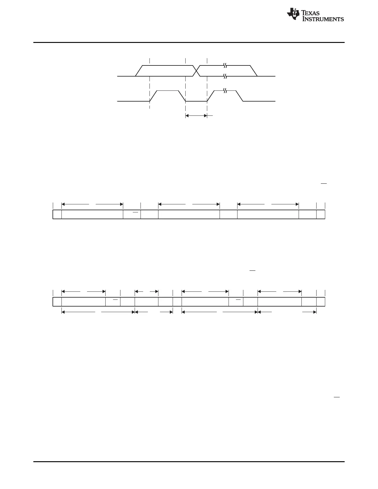
Data Line
Stable Data
Change of Data Allowed
SDA
SCL
S Slave Address R/W ACK Data ACK Data ACK P
7 8 8
1 1 1 1 1 1
1
7 8 7 8
1 1 1 1 1 1 1 1
S Slave Address
R/W
ACK
Data
ACK
S Slave Address
ACK
Data
ACK
P
1 Any
Number
1 Any Number
R/W
Operation
www.ti.com
Figure 20-4. Bit Transfer on I
2
C Bus
20.1.3 I
2
C Addressing Modes
The I
2
C module supports 7-bit addressing mode.
20.1.3.1 7-Bit Addressing
In the 7-bit addressing format (see Figure 20-5), the first byte is the 7-bit slave address and the R/W bit.
The ACK bit is sent from the receiver after each byte.
Figure 20-5. I
2
C Module 7-Bit Addressing Format
20.1.3.2 Repeated Start Conditions
The direction of data flow on SDA can be changed by the master, without first stopping a transfer, by
issuing a repeated START condition. This is called a RESTART. After a RESTART is issued, the slave
address is again sent out with the new data direction specified by the R/W bit. The RESTART condition is
shown in Figure 20-6.
Figure 20-6. I
2
C Module Addressing Format With Repeated START Condition
20.1.4 I
2
C Module Operating Modes
The I
2
C module can operate in master transmitter, master receiver, slave transmitter, or slave receiver
mode. The modes are discussed in the following sections.
20.1.4.1 Slave Mode
Initially, the I
2
C module is configured in receiver mode by setting the I2CCFG.ENS1 bit to receive the I
2
C
address. Afterwards, transmit and receive operations are controlled automatically, depending on the R/W
bit received, together with the slave address.
The I
2
C slave address is programmed with the I2CADDR.ADDR bits. The value of the I2CADDR.GC bit
determines whether the slave responds to a general call.
180
SWRU191C–April 2009–Revised January 2012
I
2
C
Submit Documentation Feedback
Copyright © 2009–2012, Texas Instruments Incorporated