Link Layer Engine
www.ti.com
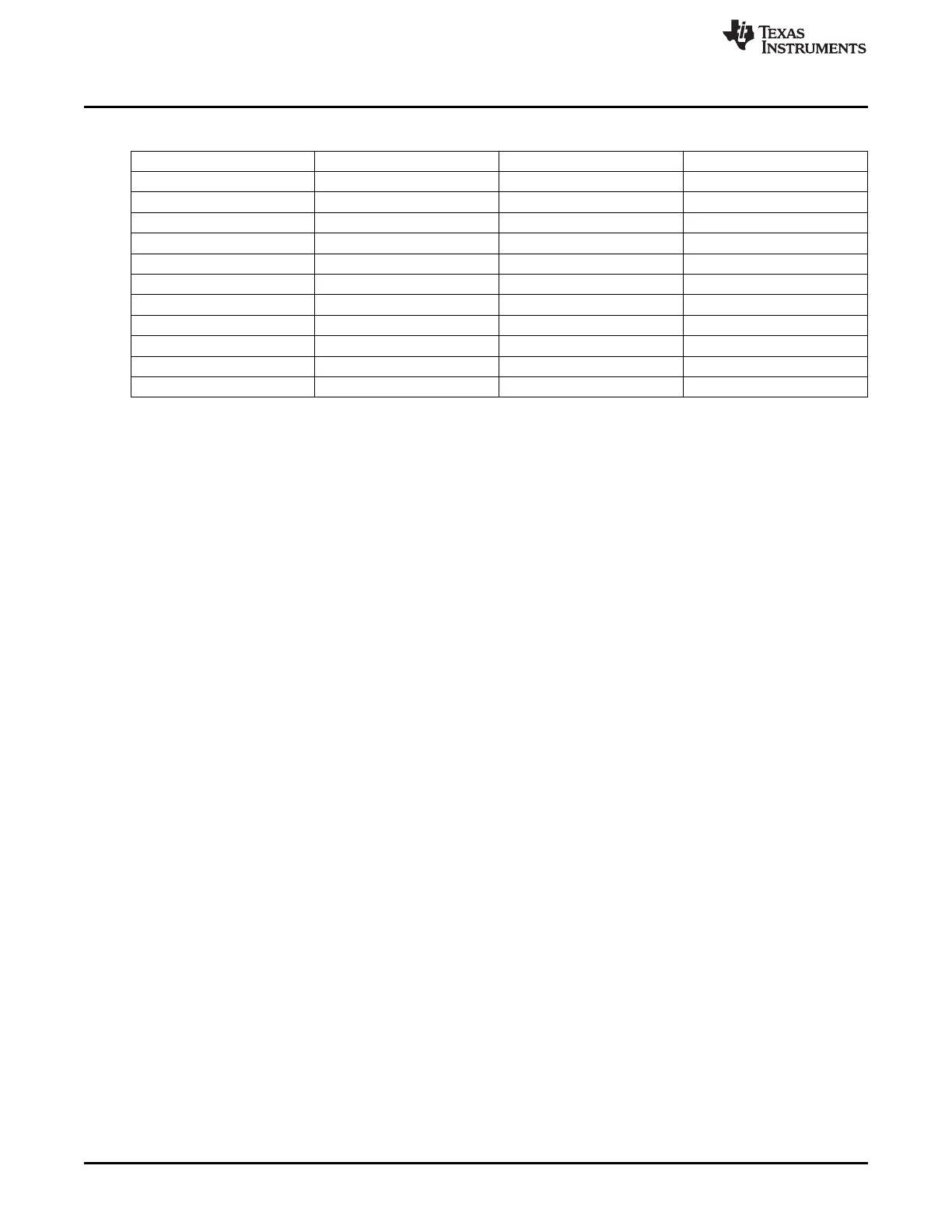
Table 25-11. Segments for Holding ACK Payload for Each Address Entry (continued)
Address Entry Number Buffer Number Setting of RFRAMCFG Start Address
2 1 1 0x6020
3 0 1 0x6040
3 1 1 0x6060
4 0 2 0x6000
4 1 2 0x6020
5 0 2 0x6040
5 1 2 0x6060
6 0 3 0x6000
6 1 3 0x6020
7 0 3 0x6040
7 1 3 0x6060
The status of buffer k for address n is contained in the PRF_ADDR_ENTRYn.ACKLENGTHk register. If the
value is 0, the buffer is free.
In order to enter a payload for address n, the MCU must follow the following procedure:
1. Read PRF_ADDR_ENTRYn.ACKLENGTH0 and PRF_ADDR_ENTRYn.ACKLENGTH1. Call the values
len_0 and len_1, respectively.
2. Read PRF_ADDR_ENTRYn.SEQSTAT.NEXTACK and call this value k. Let m be NOT k (i.e., 1 – k).
3. Check if len_k is 0. If so, write the payload to buffer k for address entry n (see Table 25-11), then write
the payload length to PRF_ADDR_ENTRYn.ACKLENGTHk. End the procedure.
4. Otherwise, check whether len_ m is 0. If so, write the payload to buffer m for address entry n (see
Table 25-11), then write the payload length to PRF_ADDR_ENTRYn.ACKLENGTHm. End the procedure.
5. Otherwise, no ACK payload buffer for that address is free, and no payload can be entered at this time.
The ACK payload length can be 1–32. When a buffer becomes free, the LLE writes the
PRF_ADDR_ENTRYn.ACKLENGTHk to 0 and raises a TXDONE interrupt.
A buffer contains only the payload to be transmitted. The length is given by
PRF_ADDR_ENTRYn.ACKLENGTHk, and the address and sequence number are as described in
Section 25.9.2.3.2.
In order to flush the buffers for address n, issue the command CMD_FLUSH_ACK n (see Table 25-12).
This causes the LLE to write PRF_ADDR_ENTRYn.ACKLENGTH0 and PRF_ADDR_ENTRYn.ACKLENGTH1
to 0 and clear PRF_ADDR_ENTRYn.SEQSTAT.ACK_PAYLOAD_SENT. If no task is running, the LLE takes
SEMAPHORE1; if it fails, it does not write to PRF_ADDR_ENTRYn.SEQSTAT.ACK_PAYLOAD_SENT. If the
transmission of an acknowledgment with payload had started on that address, flushing happens after the
transmission is finished. After the flushing is done, the LLE raises a TXFLUSHED interrupt.
25.9 Link Layer Engine
The link layer engine controls radio operation. It is started by setting the LLECTRL.LLE_EN bit to 1. The
LLE must be started before the radio can be operated.
The LLE can be reset by clearing and setting LLECTRL.LLE_EN. The LLE should not be reset while the
radio is active. The MCU should not enter PM1, PM2, or PM3 while the LLE is running a task. The mode
of the LLE is selected with LLECTRL.LLE_MODE_SEL. For the proprietary-mode operation described in
this chapter, this field must be written to 00. For BLE operation, this field is 01; that value should only be
written by the TI BLE stack. In order to switch modes, the LLE must be reset; writing to
LLECTRL.LLE_MODE_SEL while LLECTRL.LLE_EN is 1 has no effect.
314
CC2541 Proprietary Mode Radio SWRU191C– April 2009–Revised January 2012
Submit Documentation Feedback
Copyright © 2009–2012, Texas Instruments Incorporated