FREQ(6) FREQ(4)FREQ(5) FREQ(3) FREQ(1)FREQ(2) TXFREQ(0)
www.ti.com
Packet Sniffing
RFST = CMD_DEMOD_TEST;
// Wait for modem to be running
while (RFRND == 0);
// Seed RNG
RNDL = RFRND;
RNDL = RFRND;
for (j=0; j<ARRAY_SZ; j++) {
// Read 8 random bytes into CRC generation
RNDH = RFRND;
RNDH = RFRND;
RNDH = RFRND;
RNDH = RFRND;
RNDH = RFRND;
RNDH = RFRND;
RNDH = RFRND;
RNDH = RFRND;
// Read out LSB of CRC state
rndarray[j] = RNDL;
}
// Shut down radio
while (RFST != 0);
RFST = CMD_SHUTDOWN;
// Restore LNA gain setting
LNAGAIN = lnagain_stored;
25.11 Packet Sniffing
Packet sniffing is a nonintrusive way of observing data that is either being transmitted or received. The
packet sniffer outputs a clock and a data signal, which should be sampled on the rising edges of the clock.
The two packet-sniffer signals are observable as GPIO outputs. For accurate time stamping, the SFD
signal should also be output.
The packet-sniffer mode is selected in register MDMCTRL3.RFC_SNIFF_CTRL; see Table 25-22 for a
description of the different modes of operation.
Table 25-22. Packet-Sniffer Modes of Operation
MDMCTRL3.RFC_SNIFF_CTRL Description
00 Packet sniffer disabled
Data output from BSP. Tx data, including CRC, is whitened if the whitener is
01
enabled. Rx data, including CRC, is always de-whitened.
Data output from modulator. Only Tx data before whitening is output. Any CRC
10
bytes are 0.
11 Data output from the demodulator. Only Rx data before de-whitening is output.
The packet-sniffer clock frequency is equal to the RF data rate. The data is output serially, in the
received/transmitted order. It is possible to use a SPI slave to receive the data stream.
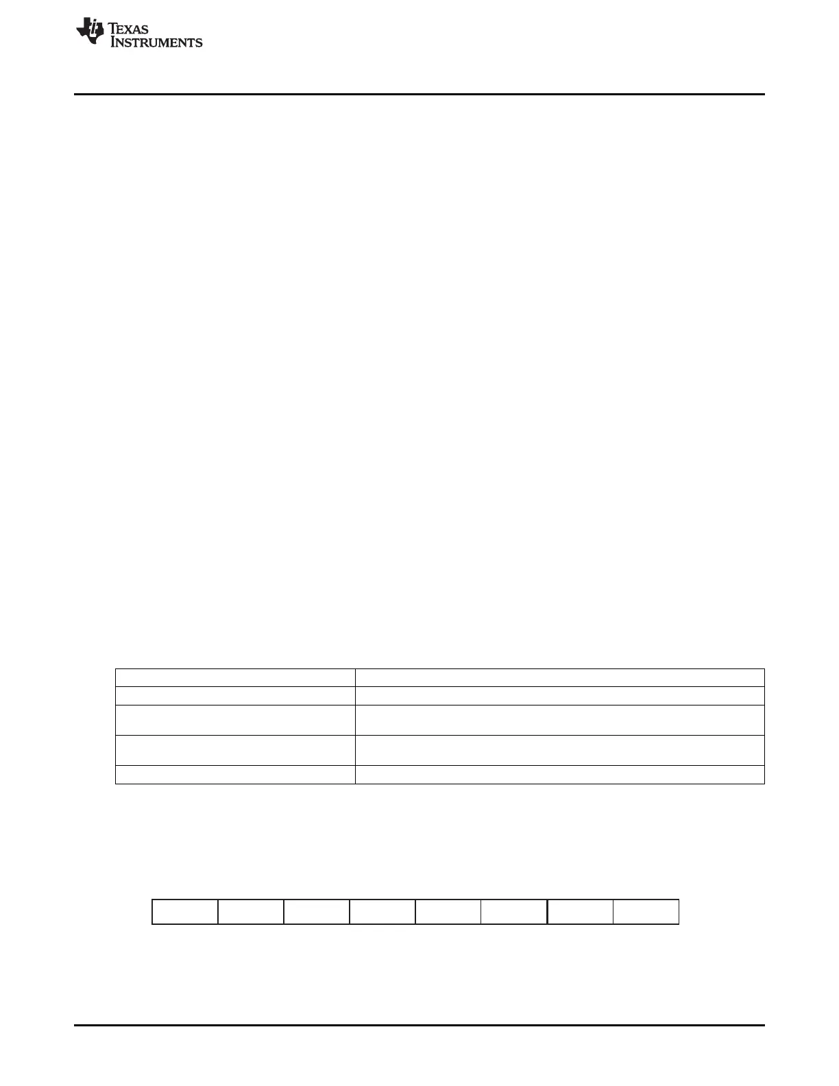
When a complete packet has been transferred, the packet sniffer appends a status byte that tells which
value of the FREQCTRL register was used and if it was a Tx or Rx packet (bit 0 is high if it was a Tx
packet). The appended byte is formatted as follows (first transmitted bit to the left):
Figure 25-14. Complete Appended Packet
This allows for the external receiver to differentiate between Rx and Tx packets.
331
SWRU191C–April 2009–Revised January 2012 CC2541 Proprietary Mode Radio
Submit Documentation Feedback
Copyright © 2009–2012, Texas Instruments Incorporated