b10 b9 b80000
1
b7
b6
b5
b4
b3
b2 b1
b0
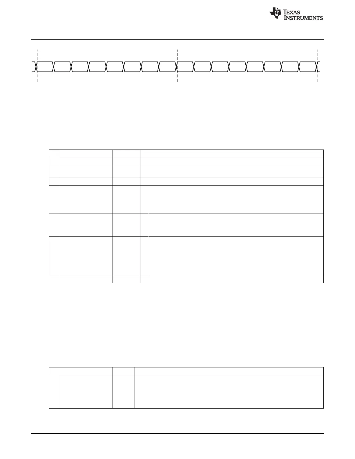
BURST_WRITECommand
Parameter
T0306-01
Debug Commands
www.ti.com
Figure 3-5. Burst Write Command (First 2 Bytes)
3.3.1 Debug Configuration
The commands WR_CONFIG and RD_CONFIG are used to access the debug-configuration data byte.
The format and description of this configuration data are shown in Table 3-2.
Table 3-2. Debug Configuration
Bit Name Reset Description
7:6 – 00 Reserved
5
SOFT_POWER_MODE
1 When set, the digital regulator is not turned off during PM2 and PM3. If this bit is
cleared, the debug interface is reset during PM2 and PM3.
4 – 0 Reserved
3
TIMERS_OFF
0
Disable timers. Disable timer operation. This overrides the TIMER_SUSPEND bit and its
function.
0: Do not disable timers
1: Disable timers
2
DMA_PAUSE
1 DMA pause. The DMA registers must not be accessed while this bit is set.
0: Enable DMA transfers
1: Pause all DMA transfers
1
TIMER_SUSPEND
1 Suspend timers.
Suspend timers when the chip is halted. The timers are also suspended during debug
instructions. When executing a STEP, the timers receive exactly (or as close as
possible) as many ticks as they would if the program were free-running.
0: Do not suspend timers
1: Suspend timers
0 – 0 Reserved. Always write 0.
3.3.2 Debug Status
A debug-status byte is read using the READ_STATUS command. The format and description of this
debug status is shown in Table 3-3.
The READ_STATUS command is, for example, used for:
• Polling the status of the chip erase (CHIP_ERASE_BUSY) after a CHIP_ERASE command.
• Checking whether the oscillator is stable (OSCILLATOR_STABLE); required for debug commands
HALT, RESUME, DEBUG_INSTR, STEP_REPLACE, and STEP_INSTR.
Table 3-3. Debug Status
Bit Name Reset Description
7
CHIP_ERASE_BUSY
0 Flash chip erase busy
The signal is only high when a chip erase is in progress. It goes high immediately after a
CHIP_ERASE command is received and returns to low when the flash is fully erased.
0: –
1: Chip erase in progress
58
Debug Interface SWRU191C–April 2009–Revised January 2012
Submit Documentation Feedback
Copyright © 2009–2012, Texas Instruments Incorporated