Pattern Sequence Mode
www.ti.com
– Trigger 1 Out Rising Edge Delay: Sets the rising edge delay of the DLPC350 TRIG_OUT_1 signal
in relation to the display of the pattern on the DMD. Each number adds 107.136 ns. Range is
–20.05 µs (before pattern exposure) to +2.79 µs (after pattern exposure) delay.
– Trigger 1 Out Falling Edge Delay: Sets the falling edge delay of the DLPC350 TRIG_IN_1 signal in
relation to the display of the pattern on the DMD. Each number adds 107.136 ns. Range is –20.05
µs (before the pattern exposure completes) to +2.79 µs (after the pattern exposure completes)
delay.
– Invert Trigger 1 Output: Sets the polarity of the TRIG_OUT_1 signal. When unchecked, the polarity
of TRIG_OUT_1 is active high. When checked, the polarity of TRIG_OUT_1 is active low.
• TRIG_OUT_2:
– Trigger 2 out Rising Edge Delay: Sets the rising edge delay of the DLPC350 TRIG_OUT_2 signal in
relation to the display of the pattern on the DMD. Each number adds 107.136 ns. Range is –20.05
µs (before pattern exposure) to +7.29 µs (after pattern exposure) delay.
– Invert Trigger 2 Output: Sets the polarity of the TRIG_OUT_2 signal. When unchecked, the polarity
of TRIG_OUT_2 is active high. When checked, the polarity of TRIG_OUT_2 is active low.
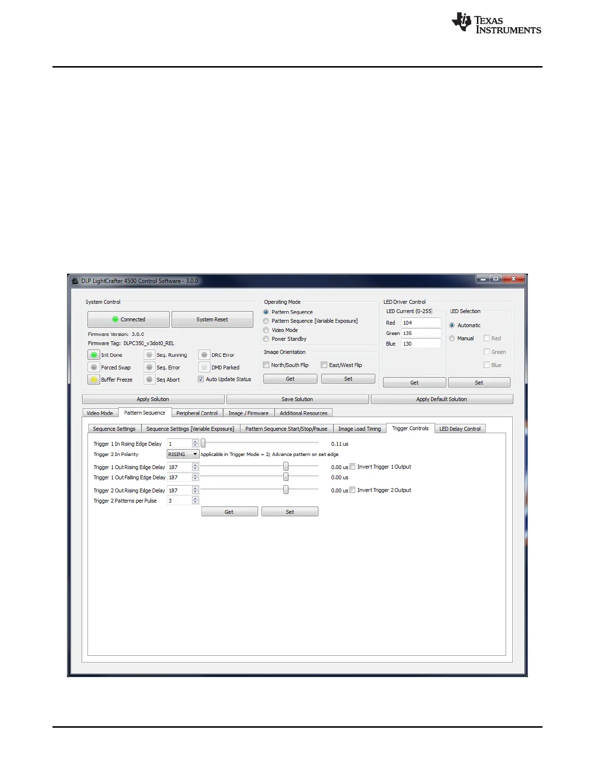
– Trigger 2 Patterns per Pulse: Indicates the number of patterns per TRIG_OUT_2 pulse.
Figure 3-9. Trigger Control Subtab
The trigger output signals are:
38
Operating the DLP LightCrafter 4500 DLPU011E–July 2013–Revised September 2015
Submit Documentation Feedback
Copyright © 2013–2015, Texas Instruments Incorporated

 Loading...


