www.ti.com
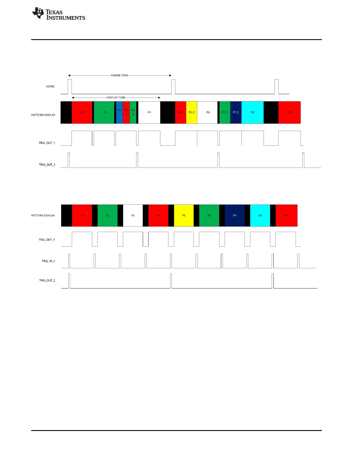
Pattern Sequence Mode
• TRIG_OUT_1 frames the exposure time of the pattern.
• TRIG_OUT_2 indicates the start of the pattern sequence or internal buffer boundary of a 24-bit-plane.
examples of signals Figure 3-10 and Figure 3-11 show.
Figure 3-10. VSYNC Pattern Trigger Mode
Figure 3-11. External Pattern Trigger Mode
3.3.5 LED Delay Control
In Pattern Sequence mode, the LED Delay Control subtab (see Figure 3-9) sets the rising and falling edge
offsets of the LED enable signals in relation to the display of the pattern on the DMD. The rising and
falling edge of the red, green, and blue LED enable signals can be independently changed between
–20.05 µs (before pattern exposure) to +7.29 µs (after pattern exposure) delay.
When the DLP LightCrafter 4500 is operating in Video Mode, set these delays to 0 (–20.05 µ s).
39
DLPU011E–July 2013–Revised September 2015 Operating the DLP LightCrafter 4500
Submit Documentation Feedback
Copyright © 2013–2015, Texas Instruments Incorporated

 Loading...


