www.ti.com
Pattern Sequence Background
Therefore, a single video frame is composed of a series of bit-planes. Because the DMD mirrors can be
either on or off, an image is created by turning on the mirrors corresponding to the bit set in a bit-plane.
With binary pulse-width modulation, the intensity level of the color is reproduced by controlling the amount
of time the mirror is on. For a 24-bit RGB frame image loaded to the DLPC350, the DLPC350 creates 24
bit-planes, stores them in its internal display buffer, and sends the bit-planes to the DLP4500 DMD, one
bit-plane at a time. Depending on the bit weight of the bit-plane, the DLPC350 controls the time this bit-
plane is exposed to light, controlling the intensity of the bit-plane. To improve image quality in video
frames, the bit-planes, time slots, and color frames are intertwined and interleaved with spatial-temporal
algorithms by the DLPC350.
For other applications where this image enhancement is not desired, the video processing algorithms can
be bypassed and replaced with a specific set of bit-planes. The bit depth of the pattern is then allocated
into the corresponding time slots. Furthermore, an output trigger signal is also synchronized with these
time slots to indicate when the image is displayed. For structured light applications, this mechanism
provides the capability to display a set of patterns and signals for the camera to capture these patterns
overlaid on an object.
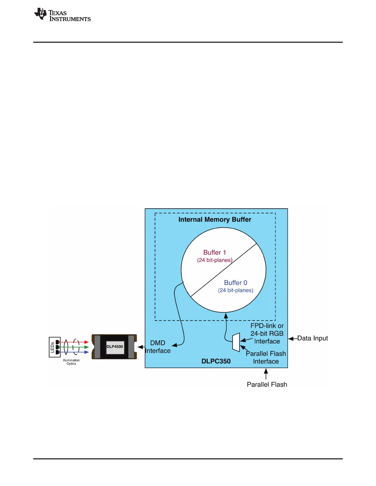
As shown in Figure 4-3, the DLPC350 stores two 24-bit frames in its internal memory buffer. This 48 bit-
plane display buffer allows the DLPC350 to send one 24-bit buffer to the DMD array while the second
buffer is filled from flash or streamed in through the 24-bit parallel RGB or FPD-link interface. In streaming
mode, the DMD array displays the previous 24-bit frame while the current frame fills the second 24-bit
frame of the display buffer. Once a 24-bit frame is displayed, the buffer rotates providing the next 24-bit
frame to the DMD. Thus, the displayed image is a 24-bit frame behind the data streamed through the 24-
bit RGB parallel or FPD-link interface.
Figure 4-3. DLPC350 Internal Memory Buffer
When the DLP LightCrafter 4500 is set to Video Mode, the displayed image is a frame delayed in relation
to the data streamed through the RGB parallel interface or FPD-link, as shown in Figure 4-4.
47
DLPU011E–July 2013–Revised September 2015 Pattern Sequences
Submit Documentation Feedback
Copyright © 2013–2015, Texas Instruments Incorporated

 Loading...


