www.ti.com
PandaBoard 4500
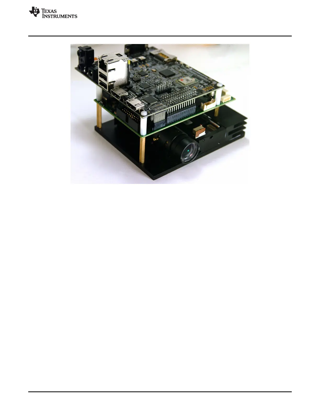
Figure 6-1. DLP LightCrafter 4500 With PandaBoard 4500
6.1.1 DLP LightCrafter 4500 to PandaBoard Interface
As shown in Figure 6-2, the DLP LightCrafter 4500 supplies 5-V power to the PandaBoard. The
PandaBoard provides 1.8 V to the DLP LightCrafter 4500 to level-shift all the signals interfacing the two
boards together. The following OMAP4 GPIOs control the routing of OMAP4 peripherals to the
corresponding DLPC350 peripherals:
• To power down the output of TFP401 and enable the level shifters in the 24-bit RGB interface, the
OMAP4 processor must drive GPIO_140 (SYS_MSTR_MUX_SEL) high.
• To connect the OMAP4 USB3 bus to the DLC350, OMAP4 must drive GPIO_39 (SYS_USB_SEL)
high.
• To connect the OMAP4 I2C2 bus to the DLPC350 I2C1 bus, OMAP4 must drive GPIO_51
(SYS_I2C_OE) high.
• To disconnect UART output of DLPC350 from J20 and route it to OMAP4 UART4, OMAP4 must drive
GPIO_33 high.
• To connect the triggers from DLPC350 to OMAP4 GPIOs, OMAP4 must drive GPIO_61
(SYS_TRIGGER_SEL) high.
Table 6-1, Table 6-2, Table 6-3, and Table 6-4 list the signals interfacing the OMAP4 processor in the
PandaBoard 4500 with the DLPC350 in the DLP LightCrafter 4500.
57
DLPU011E–July 2013–Revised September 2015 PandaBoard Interface
Submit Documentation Feedback
Copyright © 2013–2015, Texas Instruments Incorporated

 Loading...


