Modifying .ini Files
www.ti.com
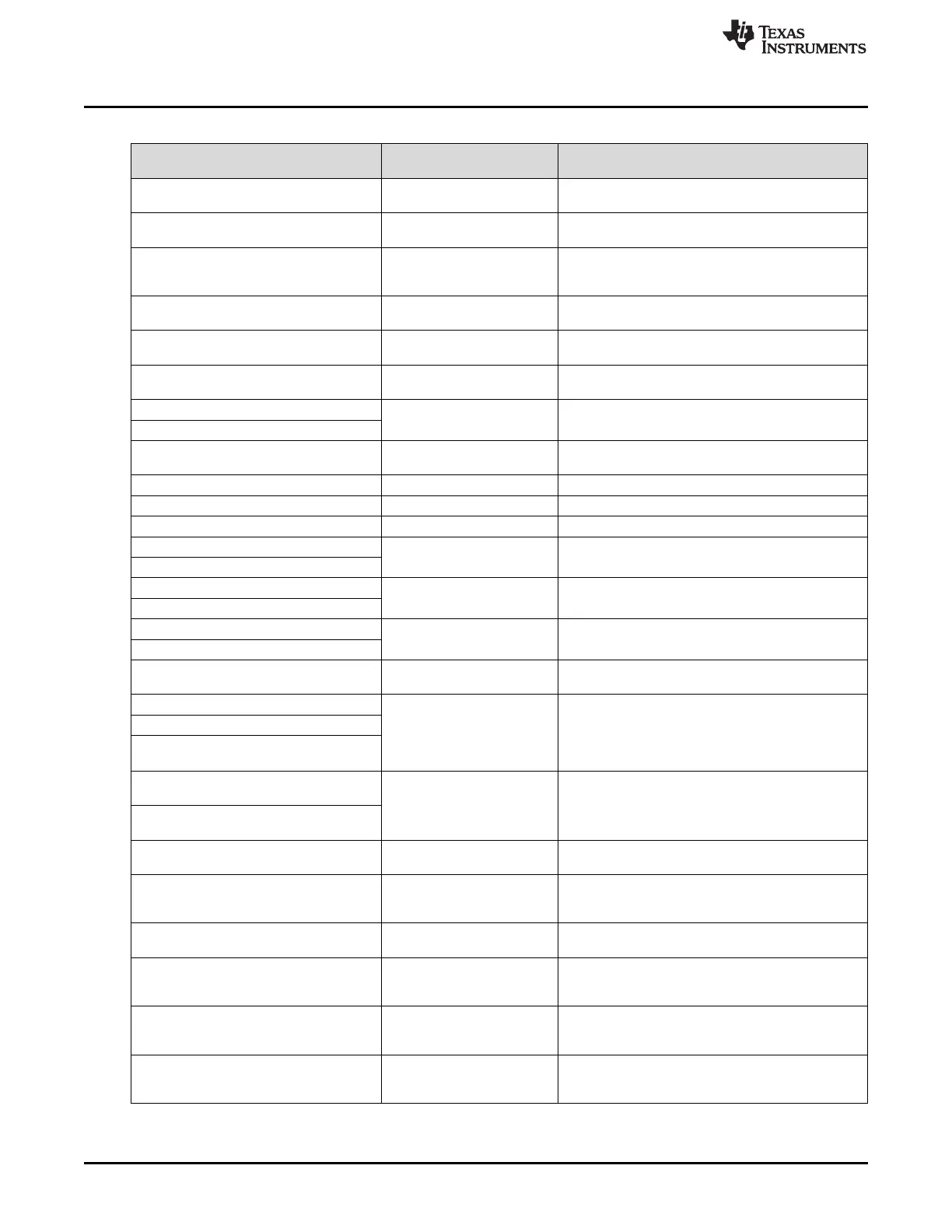
Table 5-1. List of Available Parameters when Saving Solutions
Parameter Name Programmer’s Guide Extra Notes
Command
APPCONFIG.VERSION.SUBMINOR Retrieve Firmware Version Corresponds to: Application software patch number.
Range: 0x0000 to 0xFFFF
DEFAULT.AUTOSTART N/A 0x0 = Boot normally
0x1 = Boot in standby
DEFAULT.DISPMODE Display Mode Selection 0x0 = Video mode
0x1 = Pattern display mode (will start pattern
sequence after initialization and splash time-out)
DEFAULT.SHORT_FLIP Short-Axis Image Flip 0x0 = Disable
0x1 = Enable
DEFAULT.LONG_FLIP Long-Axis Image Flip 0x0 = Disable
0x1 = Enable
DEFAULT.TRIG_OUT_1.POL Trigger Out1 Control 0x0 = Active high
0x1 = Active low
DEFAULT.TRIG_OUT_1.RDELAY Trigger Out1 Control Each can range from 0x00 and 0xD5
DEFAULT.TRIG OUT_1.FDELAY
DEFAULT.TRIG_OUT_2.POL Trigger Out2 Control 0x0 = Active high
0x1 = Active low
DEFAULT.TRIG_OUT_2.WIDTH Trigger Out2 Control Range: 0x00 to 0xFF
DEFAULT.TRIG_IN_1.DELAY Trigger In1 Control Range: 0x00 to 0xFF
DEFAULT.TRIG_IN_2.POL Trigger In2 Control For Trigger mode 2 only
DEFAULT.RED_STROBE.RDELAY Red LED Enable Control Range: 0x00 to 0xFF
DEFAULT.RED_STROBE.FDELAY
DEFAULT.GRN_STROBE.RDELAY Green LED Enable Control Range: 0x00 to 0xFF
DEFAULT.GRN_STROBE.FDELAY
DEFAULT.BLU_STROBE.RDELAY Blue LED Enable Control Range: 0x00 to 0xFF
DEFAULT.BLU_STROBE.FDELAY
DEFAULT.INVERTDATA Pattern Display Invert Data 0x0 = Typical operation
0x1 = Inverted operation
DEFAULT.LEDCURRENT_RED LED Driver Current Control Range: 0x00 to 0xFF. On this reference design, 0x0
is the maximum PWM, and 0xFF is the minimum. If
DEFAULT.LEDCURRENT_GRN
multiple LEDs are enabled simultaneously (pattern
DEFAULT.LEDCURRENT_BLU
mode or manual operation), then be mindful of
maximum current values for design.
DEFAULT.PATTERNCONFIG.PAT_ Pattern Display Exposure and PAT_EXPOSURE must be less than PAT_PERIOD
EXPOSURE Frame Period by at least 230 µs, or it must be equal to
PAT_PERIOD.
DEFAULT.PATTERNCONFIG.PAT_
PERIOD
DEFAULT.PATTERNCONFIG.PAT_MODE Pattern Display Data Input 0x0 = Streaming patterns through video ports
Source 0x3 = Flash memory
DEFAULT.PATTERNCONFIG.TRIG_ Pattern Trigger Mode 0x0 = Vsync trigger
MODE Selection 0x1 = Internal or external trigger
0x2 = Alternating trigger (not currently in GUI)
DEFAULT.PATTERNCONFIG.PAT_ Pattern Display LUT Control 0x0 = Play once
REPEAT 0x1 = Repeat the pattern sequence
DEFAULT.PATTERNCONFIG.NUM_ Pattern Display LUT Control Must be less than 63 (where 0x0 = 1, and 0x3F = 64).
SPLASH Must equal number of items in
DEFAULT.SPLASHLUT
DEFAULT.SPLASHLUT Pattern Display LUT Flash image indexes in the order they appear in the
Data–Image Index pattern sequence. (Example: DEFAULT.SPLASHLUT
0x1 0x2 0x1 0x3 0x0 0x2)
DEFAULT.PATTERNCONFIG.NUM_LUT_ Pattern Display LUT Control Must be less than 128 (where 0x0 = 1, and 0x7F =
ENTRIES 128). Must equal number of items in
DEFAULT.SEQPATLUT.
52
Saving Solutions DLPU011E–July 2013–Revised September 2015
Submit Documentation Feedback
Copyright © 2013–2015, Texas Instruments Incorporated

 Loading...


