Pattern Sequence Background
www.ti.com
Figure 4-4. Frame Delay Between Parallel Interface Input and Projection Output
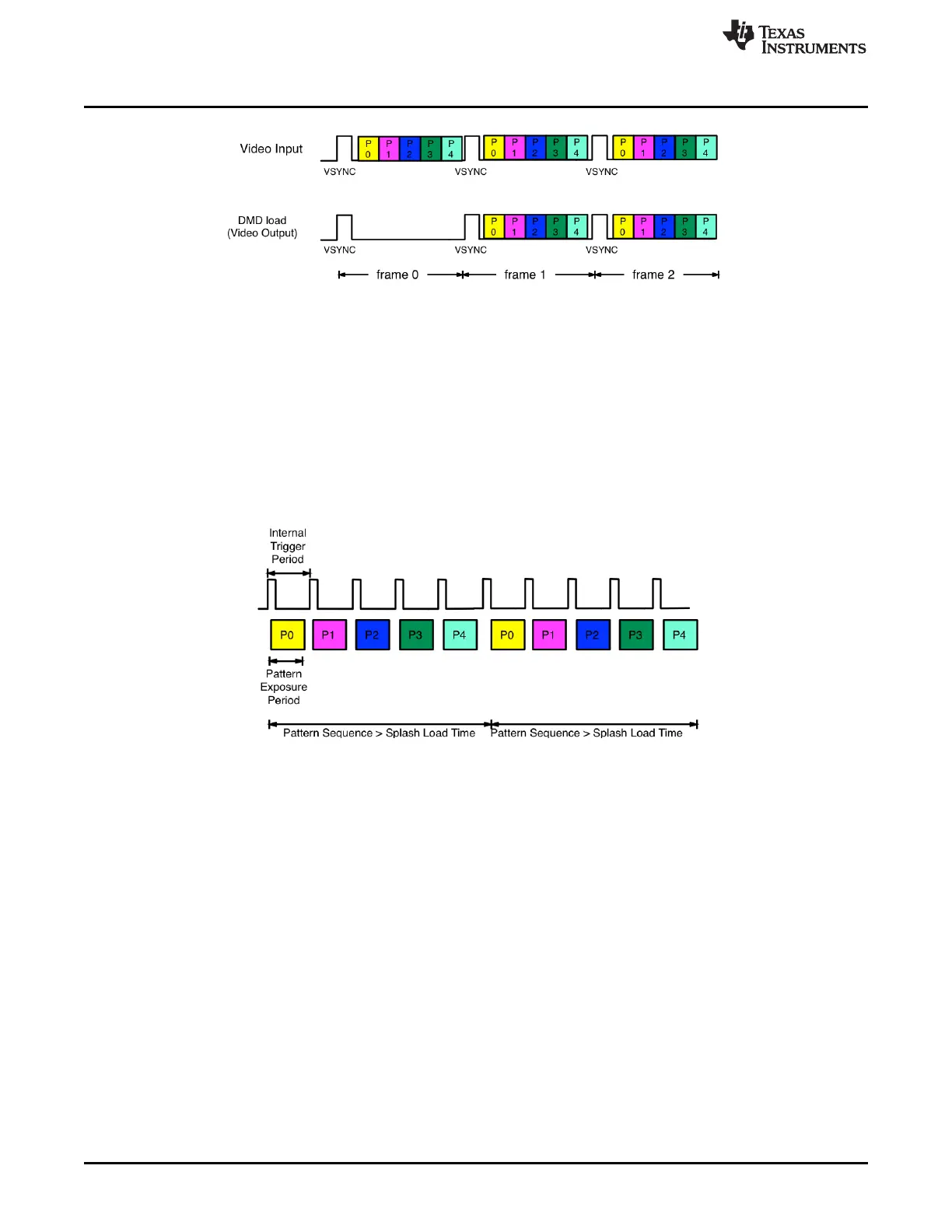
When the DLP LightCrafter 4500 is set to Pattern Sequence mode with pattern source from flash, the
pattern sequence must be loaded from flash memory. The DLPC350 takes at-worst-case 200 ms to load
one buffer (24 bit-planes). The actual time to load the buffer depends on the complexity of the image. The
actual time is provided in the Image / Firmware tab under Image Load Time. If the pattern sequence is
less than 24 bit fields, the patterns are displayed from a preloaded buffer. Once the patterns are loaded,
the pattern sequence repeats from the internal display memory with no buffer load penalty. If the pattern
sequence is greater than 24 bit-fields, the 24 bit-field pattern sequence display time must be longer than
the full buffer load time. This provides enough time to load the next buffer while the current buffer is
displayed. See Figure 4-5 for a diagram of Image Load Time, Pattern Exposure Trigger period, and
Internal Trigger period.
Figure 4-5. Image Load Time and Pattern Sequence Timing
In pattern sequence mode, the 48 bit-planes can be preloaded from flash memory and then sequenced
with a combination of patterns with different bit depths. To synchronize a camera to the displayed
patterns, the DLPC350 supports two trigger inputs and two trigger outputs. TRIG_IN_1 pulse indicates to
the DLPC350 to advance to the next pattern, while TRIG_IN_2 starts and stops the pattern sequence.
TRIG_OUT_1 frames the exposure time of the pattern, while TRIG_OUT_2 indicates the start of the
pattern sequence or internal buffer boundary of 24 bit-planes. For example, in Figure 3-10, the VSYNC
starts the pattern sequence display. The pattern sequence consists of a series of three consecutive
patterns. The first pattern sequence consists of P1, P2, and P3. P3 is an RGB pattern, it is shown with its
time-sequential representation of P3.1, P3.2, and P3.3. The second pattern sequence consists of three
patterns: P4, P5, and P6. The third sequence consists of P7, P8, and P9. TRIG_OUT_1 frames each
pattern exposed, while TRIG_OUT_2 indicates the start of each of the three pattern sequences. In
Figure 3-11, a pattern sequence of a group of four patterns are displayed. TRIG_OUT_1 frames each
pattern exposed, while TRIG_OUT_2 indicates the start of each four-pattern sequence. TRIG_IN_1 pulses
advance the pattern.
48
Pattern Sequences DLPU011E–July 2013–Revised September 2015
Submit Documentation Feedback
Copyright © 2013–2015, Texas Instruments Incorporated

 Loading...


