139
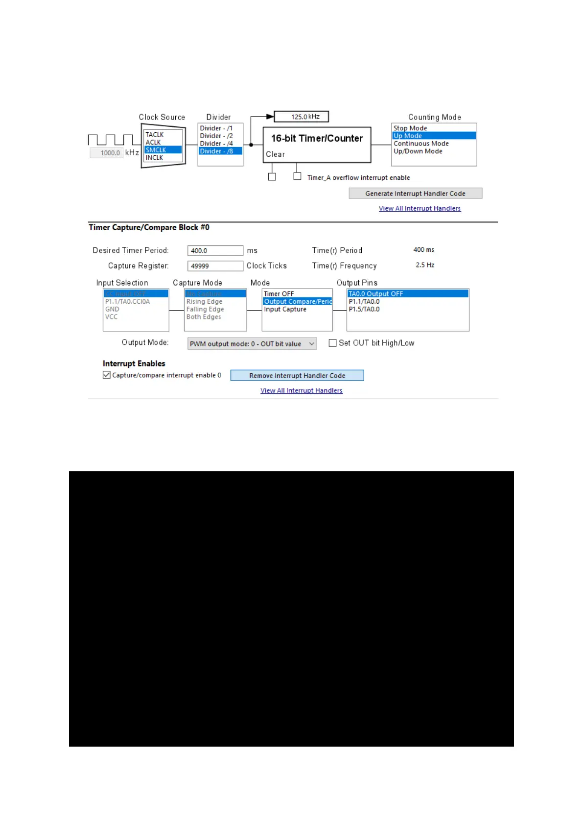
source. Note that in the diagram below timer overflow interrupt is not being used. Timer capture-
compare interrupt is used instead.
The desire time period is set for 400ms or 2.5Hz. At every 400ms interval, a compare-match interrupt
will occur. How this is done? Well the timer is set for up counting and it has an input clock of 125kHz
– 1MHz SMCLK prescaled by 8.
void Timer0_A3_graceInit(void)
{
/* USER CODE START (section: Timer0_A3_graceInit_prologue) */
/* User initialization code */
/* USER CODE END (section: Timer0_A3_graceInit_prologue) */
/*
* TA0CCTL0, Capture/Compare Control Register 0
*
* CM_0 -- No Capture
* CCIS_0 -- CCIxA
* ~SCS -- Asynchronous Capture
* ~SCCI -- Latched capture signal (read)
* ~CAP -- Compare mode
* OUTMOD_0 -- PWM output mode: 0 - OUT bit value
*
* Note: ~<BIT> indicates that <BIT> has value zero
*/
TA0CCTL0 = CM_0 | CCIS_0 | OUTMOD_0 | CCIE;
/* TA0CCR0, Timer_A Capture/Compare Register 0 */
TA0CCR0 = 49999;
/*