0 ... 111
0 ... 101
0 ... 100
0 ... 011
0 ... 010
0 ... 001
0 ... 000
0
1 2
3
4
5
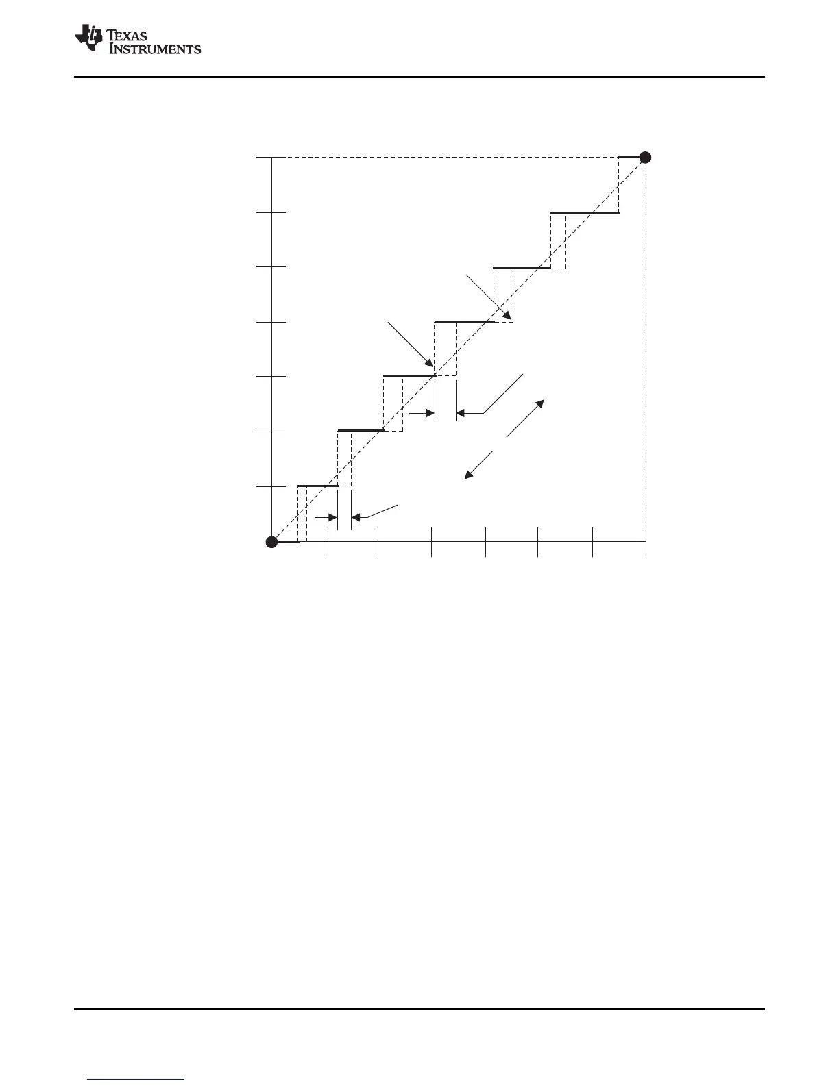
Digital Output Code
Analog Input Value (LSB)
0 ... 110
6
7
At Transition
011/100
(–½ LSB)
At Transition
001/010 (–1/4 LSB)
Actual
Transition
Ideal
Transition
End-Point Lin. Error
119
TMS570LS0714
www.ti.com
SPNS226E –JUNE 2013–REVISED NOVEMBER 2016
Submit Documentation Feedback
Product Folder Links: TMS570LS0714
Peripheral Information and Electrical SpecificationsCopyright © 2013–2016, Texas Instruments Incorporated
The integral nonlinearity error shown in Figure 7-14 (sometimes referred to as linearity error) is the
deviation of the values on the actual transfer function from a straight line.
A. 1 LSB = (AD
REFHI
– AD
REFLO
)/2
12
Figure 7-14. Integral Nonlinearity (INL) Error
(A)
 Loading...


