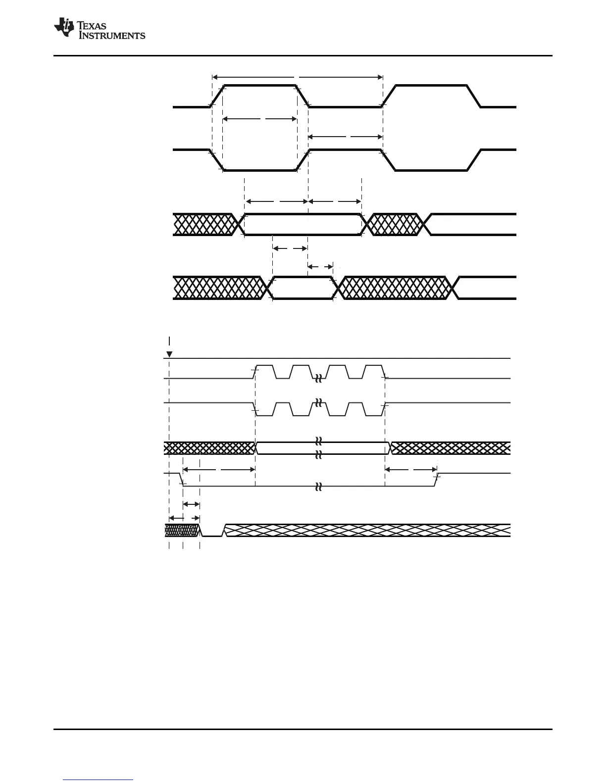
EasyManuals Logo

Texas Instruments TMS570LS0714 User Manual

Texas Instruments TMS570LS0714
162 pages
To Next Page IconTo Next Page
To Previous Page IconTo Previous Page
Page #137 background image
SPICLK
(clock polarity=0)
SPISIMO
SPICSn
Master Out Data Is Valid
9
SPICLK
(clock polarity=1)
SPIENAn
10
Write to buffer
11
8
SPISOMI
SPISIMO
SPICLK
(clock polarity = 1)
SPICLK
(clock polarity = 0)
Master In Data
Must Be Valid
Master Out Data Is Valid
3
2
1
54
66
7
137
TMS570LS0714
www.ti.com
SPNS226E JUNE 2013REVISED NOVEMBER 2016
Submit Documentation Feedback
Product Folder Links: TMS570LS0714
Peripheral Information and Electrical SpecificationsCopyright © 2013–2016, Texas Instruments Incorporated
Figure 7-20. SPI Master Mode External Timing (CLOCK PHASE = 0)
Figure 7-21. SPI Master Mode Chip-Select Timing (CLOCK PHASE = 0)

Table of Contents

Questions and Answers:

Question and Answer IconNeed help?

Do you have a question about the Texas Instruments TMS570LS0714 and is the answer not in the manual?

Texas Instruments TMS570LS0714 Specifications

General IconGeneral
CoreARM Cortex-R4F
Clock Speed80 MHz
RAM64 KB
Operating Temperature-40°C to 125°C
Operating Voltage3.0 V to 3.6 V
Watchdog TimerYes
Communication InterfacesCAN, SPI, UART
PackageLQFP
Safety FeaturesECC
ADC12-bit ADC

Related product manuals