27
TMS570LS0714
www.ti.com
SPNS226E –JUNE 2013–REVISED NOVEMBER 2016
Submit Documentation Feedback
Product Folder Links: TMS570LS0714
Terminal Configuration and FunctionsCopyright © 2013–2016, Texas Instruments Incorporated
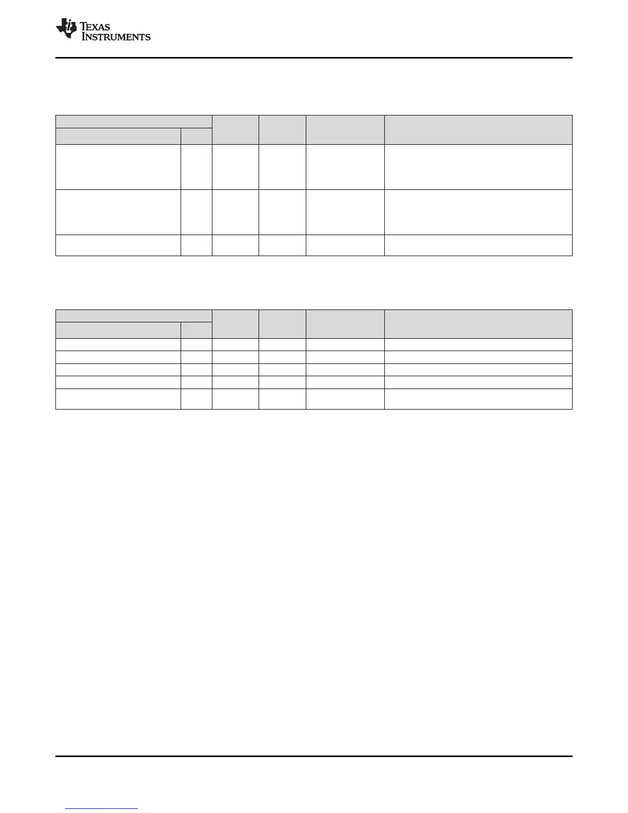
4.2.2.11 System Module Interface
Table 4-30. PZ System Module Interface
TERMINAL
SIGNAL
TYPE
RESET
PULL
STATE
PULL TYPE DESCRIPTION
SIGNAL NAME 100 PZ
nPORRST 31 Input Pullup 100 µA
Power-on reset, cold reset External power supply
monitor circuitry must drive nPORRST low when any of
the supplies to the microcontroller fall out of the
specified range. This terminal has a glitch filter. See
Section 6.8.
nRST 81 I/O Pullup 100 µA
The external circuitry can assert a system reset by
driving nRST low. To ensure that an external reset is not
arbitrarily generated, TI recommends that an external
pullup resistor is connected to this terminal. This
terminal has a glitch filter. See Section 6.8.
nERROR 82 I/O Pulldown 20 µA
ESM Error Signal. Indicates error of high severity. See
Section 6.8.
4.2.2.12 Clock Inputs and Outputs
Table 4-31. PZ Clock Inputs and Outputs
TERMINAL
SIGNAL
TYPE
RESET
PULL
STATE
PULL TYPE DESCRIPTION
SIGNAL NAME 100 PZ
OSCIN 14 Input – – From external crystal/resonator, or external clock input
KELVIN_GND 15 Input – – Dedicated ground for oscillator
OSCOUT 16 Output – – To external crystal/resonator
ECLK 84 I/O Pulldown Programmable, 20 µA External prescaled clock output, or GIO.
GIOA[5]/INT[5]/EXTCLKIN/EPWM1A
/N2HET1_PIN_nDIS
10 Input Pulldown 20 µA External Clock In
 Loading...


