3.3 V
1.2 V
V
CC
(1.2 V)
V
CCIO
/ V
CCP
(3.3 V)
8
6
3
7
6
9
V
CCPORH
V
CCIOPORL
V
IL(PORRST)
V
CCIOPORH
7
V
CCIOPORH
V
CCIOPORL
V
CCPORL
V
CC
nPORRST
V
CCIO
/ V
CCP
V
CCPORH
V
CCPORL
V
IL
V
IL
V
IL
V
IL
V
IL(PORRST)
45
TMS570LS0714
www.ti.com
SPNS226E –JUNE 2013–REVISED NOVEMBER 2016
Submit Documentation Feedback
Product Folder Links: TMS570LS0714
System Information and Electrical SpecificationsCopyright © 2013–2016, Texas Instruments Incorporated
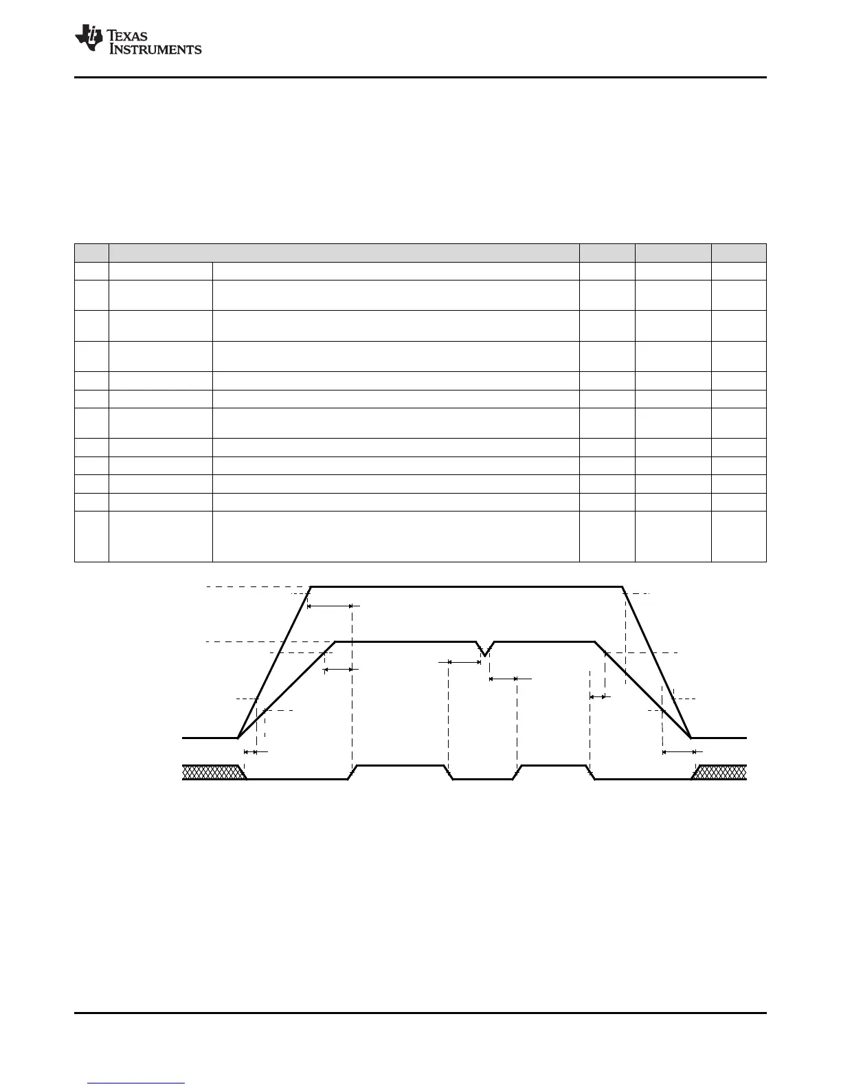
6.3.3 Power-On Reset: nPORRST
This is the power-on reset. This reset must be asserted by an external circuitry whenever any power
supply is outside the specified recommended range. This signal has a glitch filter on it. It also has an
internal pulldown.
6.3.3.1 nPORRST Electrical and Timing Requirements
Table 6-4. Electrical Requirements for nPORRST
NO. MIN MAX UNIT
V
CCPORL
V
CC
low supply level when nPORRST must be active during power up 0.5 V
V
CCPORH
V
CC
high supply level when nPORRST must remain active during power
up and become active during power down
1.14 V
V
CCIOPORL
V
CCIO
/ V
CCP
low supply level when nPORRST must be active during
power up
1.1 V
V
CCIOPORH
V
CCIO
/ V
CCP
high supply level when nPORRST must remain active
during power up and become active during power down
3.0 V
V
IL(PORRST)
Low-level input voltage of nPORRST V
CCIO
> 2.5 V 0.2 * V
CCIO
V
Low-level input voltage of nPORRST V
CCIO
< 2.5 V 0.5 V
3 t
su(PORRST)
Setup time, nPORRST active before V
CCIO
and V
CCP
> V
CCIOPORL
during
power up
0 ms
6 t
h(PORRST)
Hold time, nPORRST active after V
CC
> V
CCPORH
1 ms
7 t
su(PORRST)
Setup time, nPORRST active before V
CC
< V
CCPORH
during power down 2 µs
8 t
h(PORRST)
Hold time, nPORRST active after V
CCIO
and V
CCP
> V
CCIOPORH
1 ms
9 t
h(PORRST)
Hold time, nPORRST active after V
CC
< V
CCPORL
0 ms
t
f(nPORRST)
Filter time nPORRST pin;
pulses less than MIN will be filtered out, pulses greater than MAX will
generate a reset.
475 2000 ns
A. Figure 6-1 shows that there is no timing dependency between the ramp of the V
CCIO
and the V
CC
supply voltages.
Figure 6-1. nPORRST Timing Diagram
(A)
 Loading...


