EN - 20
6 Setting up the power supply EX-TRAFIRE
®
45HD
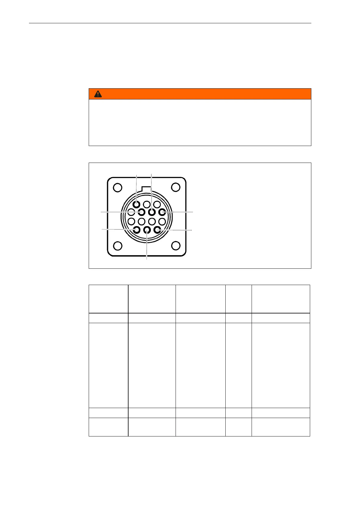
6.6 Connecting the CNC interface
The CNC interface is on the rear of the device. Control signals can be
transmitted via the CNC interface. The signal types can be found in
table 10. The control elements are located on the control panel. The
connections are on the front and rear of the device.
4.1 Assembly and use on page EN-9
Electric shock due to live parts
Live parts are exposed when the housing is open. This can result in fatal
electric shock.
• Set the <POWER> switch to <OFF> and disconnect the input power
plug before opening the housing.
Fig. 4 Pin assignment for CNC interface
Table 10 Pin assignment
Signal START
Start plasma
cutting
Arc
Start feeding
PE Voltage divider
Type Input Output PE Output
Notice Open by
default.
Requires
potential-free
contact to
close.
Open by
default.
Potential-free
with max.
capacity of:
120 V AC/1 A
Reduced arc
signal:
20:1
21.1:1
30:1
40:1
50:1
(supplies max.
10 V)
PIN 3, 4 12, 14 13 6 (+), 5 (-)
Internal
cable color
Yellow, yellow White, white Green/
yellow
6 (red), 5 (white)