CUTMASTER 40mm
PARTS REPLACEMENT 7-2 Manual 0-5085
7.04 Major External Parts
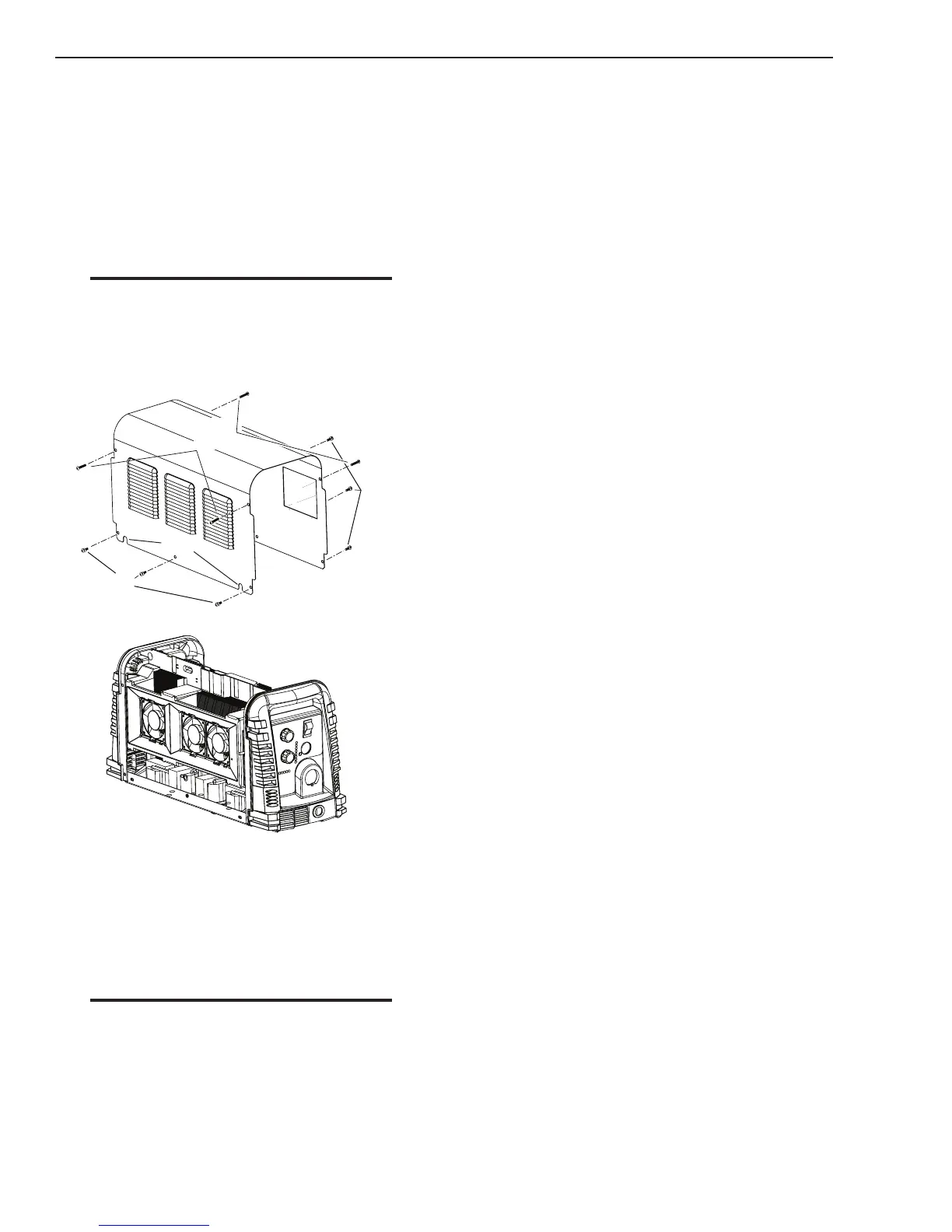
A. Cover Removal
Tools required: T20 Torx Driver
1. Remove the upper and lower screws which
secure the cover to the main assembly. Do not
loosen the lower screws inside the cut out slots
in the bottom of the cover.
NOTE
The upper screws and lower screws are not the
same. Do not mix them. The upper screws are
for threading into the plastic of the front and
rear panels. DO NOT use the finer threaded
lower screws for this.
Art # A-08429
Lower
Screws
Lower
Screws
Slots
Upper
Screws
2. Carefully pull the Cover up and away from the
unit.
B. Cover Installation
1. Reverse previous procedures for cover installa-
tion.
NOTE
When installing the upper screws, attempt to
reuse the original threads. The easiest way
to do this is by turning the screw counter-
clockwise until you feel the threads line up,
then begin to turn the screw clockwise to
tighten. Do not over tighten.
C. Tube Handle Replacement
Tools required: T20 Torx Driver
1. Remove the cover per subsection 7.04-A.
2. Remove the screws securing the tube handles to
the base of the unit.
3. Remove the Tube Handles.
4. Replace the Tube Handles by reversing the above
steps.
5. Reinstall the power supply cover.
D. Disconnecting Front and Rear Panels from
the base
In many of the replacement procedures, it may be help-
ful to disconnect the front or rear panel from the base in
order to allow more room to access the parts.
Tools required: T20 Torx Driver
1. Remove the cover per subsection 7.04-A.
2. While grasping the panel close to the base, pull
the panel directly from the base to release the
locking tabs.
3. To re-engage the panel, position the panel so that
the locking tabs are above the base, then push the
panel back onto the base until the locking tabs
engage the mating holes in the base.
4. For complete removal of panel, disconnect any
other item still attached to the panel and another
component of the power supply.

 Loading...


